Display unit and electronic apparatus with display unit

a technology of electronic equipment and display unit, which is applied in the field of display system, can solve the problems of lowering the resolution of the plane image display, difficult switching between the presence and absence of the lenticular lens system, and unsatisfactory and uncomfortable feeling, and achieves the effect of high quality stereoscopic vision and little crosstalk

Active Publication Date: 2007-05-01
TRIVALE TECH
View PDF10 Cites 77 Cited by
  • Summary
  • Abstract
  • Description
  • Claims
  • Application Information

AI Technical Summary

Benefits of technology

[0011]According to the display system that includes the light guiding plate; the light sources disposed at two different light input ends of the light guiding plate; the double-sided prism sheet that is disposed on a light emitting face side of the light guiding plate, and that has on a first surface facing the light guiding plate a triangular prism bank extending in a direction parallel to the light input ends of the light guiding plate, and on a second surface opposite to the first surface a cylindrical lens bank extending in a direction parallel to the triangular prism bank; the transmissive display panel disposed on a light emitting face side of the double-sided prism sheet; and the synchronization driving section for causing the transmissive display panel to display parallactic images in synchronization with the light sources, wherein the light rays from the light sources are emitted through the transmissive display panel at the angles corresponding to the right and left parallax. Thus, the display system offers advantages of being able to achieve high quality stereoscopic vision with little crosstalk and to display different frames simultaneously on the same screen.

Problems solved by technology

Thus, to present the stereoscopic display to the observer, the observer must wear the spectacles, which involves an unpleasant and uncomfortable feeling.
In addition, it is difficult for the lenticular lens system to switch between the presence and absence of the lenticular lens.
Consequently, to display a plane image, the lenticular lens system must display different pixel lines to the two eyes as in the case of the stereoscopic image, thereby lowering the resolution of the plane image display.
However, since the parallax barrier system cuts off part of light rays from a light source with the parallax barrier during the stereoscopic display, it presents a problem of darkening the display.
Although the method can carry out the stereoscopic display without lowering the resolution, it has a problem of decreasing light efficiency and darkening display because it cuts off part of the light rays from the light source to create the stripe-like light sources.
In addition, since it requires expensive liquid crystal shutter elements in addition to the display panel to create the stripe-like light sources, it has a problem of being unable to implement a low-cost system.
Since the method controls the directivity of the illuminating light by only the adjustment of the light emitting luminous intensity distribution from the light guiding plates, it is more difficult for the method to obtain the sufficient directivity than the foregoing system that can determine the directivity of the illuminating light explicitly by the shutter elements and the collimator lens.
Thus, it has problems in that it easily brings about crosstalk between right and left because of the degradation in the directivity, and it must prepare two pairs of the light guiding plates as in the foregoing Japanese patent application laid-open No. 2001-66547 to obtain good luminous intensity distribution characteristics.
First, the method of using the spectacles has inconvenience of wearing the spectacles.
As for the spectacleless method, the method of using the lenticular or parallax barrier has a problem of decreasing the resolution of the stereoscopic image or plane image, or reducing the brightness.
As for the conventional method of switching the directivity of light, the method of using the switching shutter elements and collimator lens is costly because it requires expensive switching shutter elements.
The method of directly controlling the directivity of light by the light guiding plates has a problem of easily bringing about crosstalk between right and left because of the difficulty of controlling the directivity, and a problem of complicating the configuration and being expensive because it uses two pairs of the backlights.

Method used


Image

  • Display unit and electronic apparatus with display unit
  • Display unit and electronic apparatus with display unit
  • Display unit and electronic apparatus with display unit

Examples


embodiment 1

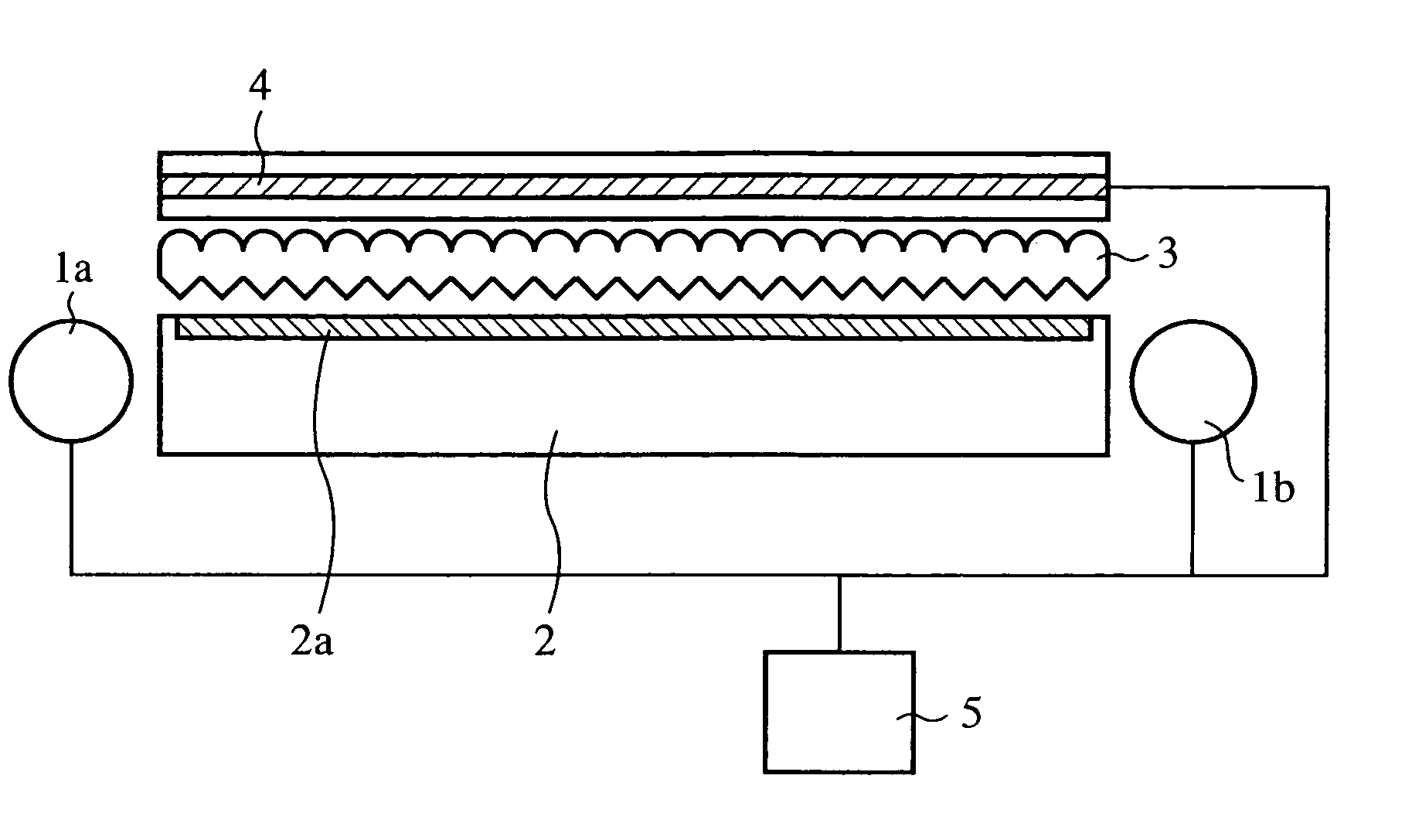
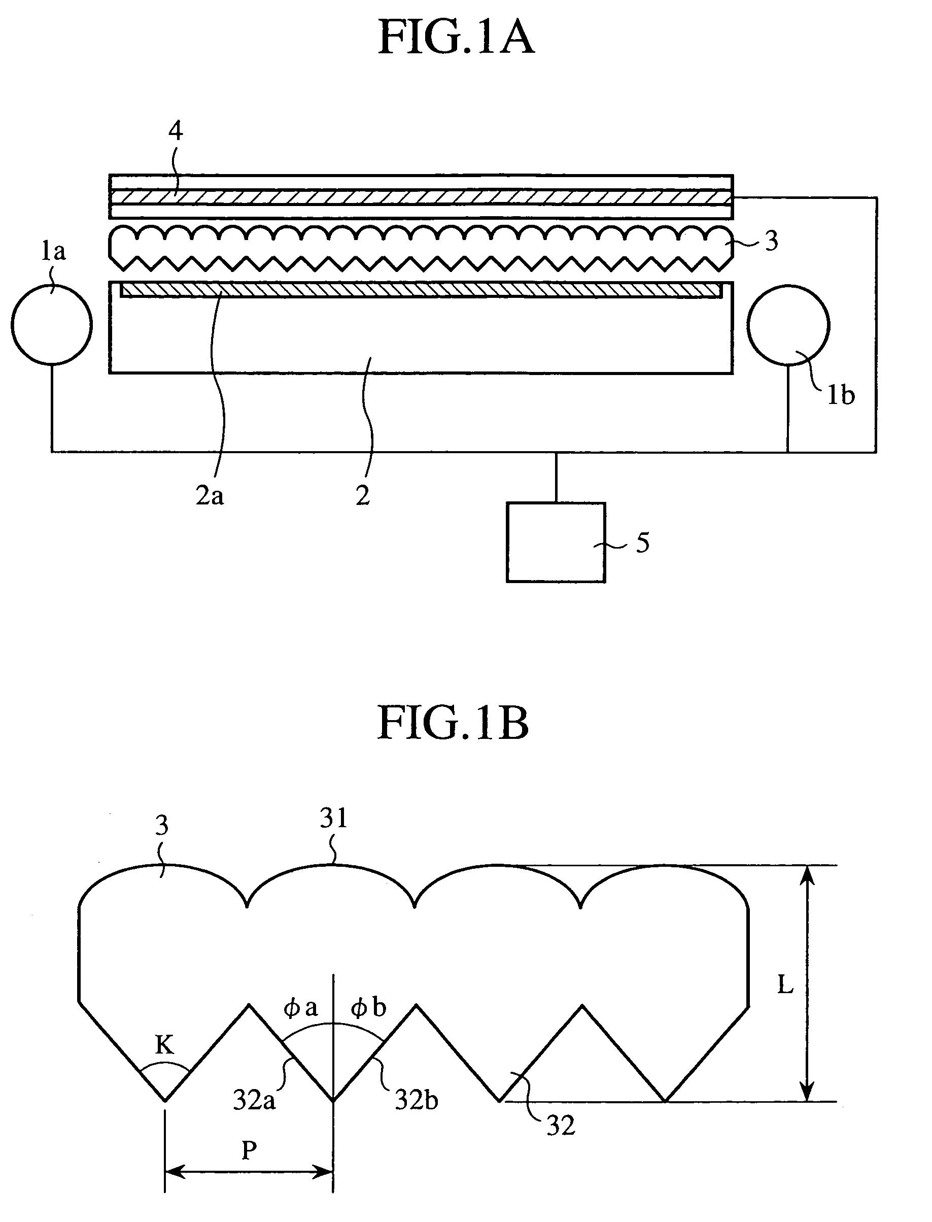
[0036]FIGS. 1A and 1B are side views illustrating a main portion of a display system for a portable information apparatus of an embodiment 1 in accordance with the present invention.

[0037]In FIGS. 1A and 1B A, reference numerals 1a and 1b each designate a light source, and the reference numeral 2 designates a light guiding plate which has a rectangular side and is flat-shaped as a whole, and has a predetermined width in the direction normal to the sheet of paper. At both light input ends of the light guiding plate 2, the light sources 1a and 1b are placed oppositely. The reference numeral 2a designates a light extracting section formed on a surface of the light guiding plate 2 by reflection print, rough surface processing or the like.

[0038]The reference numeral 3 designates a double-sided prism sheet placed on the emitting surface of the light guiding plate 2, and 4 designates a transmissive liquid crystal panel, in which a shaded portion designates a liquid crystal layer.

[0039]The ...

embodiment 2

[0068]FIG. 20 is a front view illustrating an electronic information apparatus of an embodiment 2 in accordance with the present invention. Here, to describe the details of the display system, an interior portion of the electronic information apparatus is shown in the periphery of the display system.

[0069]In FIG. 20, the electronic information apparatus, a portable electronic notepad, has in its body 10 light sources 1a and 1b placed face to face on the right and left side of a light guiding plate 2. The light sources 1a and 1b include a light-emitting diode 8 and a light guide 9. The light output from the light-emitting diode 8, traveling through the light guide 9, gradually radiates toward the light guiding plate 2, thereby radiating uniformly to the sides of the light guiding plate 2.

[0070]The reference numeral 3 designates a double-sided prism sheet mounted on the emitting surface of the light guiding plate 2. The double-sided prism sheet 3 has a triangular prism bank and a cyli...

embodiment 3

[0074]FIG. 21 is a structural diagram illustrating an electronic information apparatus and display system of an embodiment 3 in accordance with the present invention.

[0075]In FIG. 21, the electronic information apparatus, a portable telephone 12, includes a display system of the embodiment 1. The display system is disposed in such a fashion that it displays different images in upper and lower portions. In other words, the light sources 1c and 1d are placed opposingly at the top and bottom of the light guiding plate 2. The reference numeral 3 designates a double-sided prism sheet disposed on the emitting surface of the light guiding plate 2. The triangular prism bank and cylindrical prism bank of the double-sided prism sheet 3 extend in the lateral direction. The reference numeral 4 designates a transmissive liquid crystal panel mounted on the double-sided prism sheet. Since the other details of the display system are the same as those of the embodiment 1, their description is omitte...


PUM


Abstract

A display system includes respective light sources disposed at two opposed light input ends of a light guiding plate. A double-sided prism sheet is disposed on a light-emitting side of the light guiding plate and includes, on a first surface facing the light guiding plate, a triangular prism bank extending in a direction parallel to the light input ends of the light guiding plate. The double-sided prism sheet includes, on a second surface, opposite to the first surface, a cylindrical lens bank extending in a direction parallel to the triangular prism bank. A transmissive display panel is disposed on a light-emitting side of the double-sided prism sheet. A synchronization driving section alternatively illuminates the respective light sources so the transmissive display panel displays two different images. The light from the light sources is emitted through the transmissive display panel at respective divergent angles producing two images corresponding to right and left parallax images, producing a stereoscopic display.

Description

TECHNICAL FIELD[0001]The present invention relates to a display system, and particularly to a display system that is used for a mobile information terminal including a small display screen, and that enables stereoscopic vision and simultaneous display of different frames on the same screen.BACKGROUND ART[0002]A stereoscopic display system usually presents the two eyes of an observer with images with parallax from individual viewpoints. As methods of presenting the two eyes of the observer with images with parallax, there are two conventional methods: a method of using a pair of special spectacles; and a spectacleless method.[0003]The method of using the spectacles switches right and left parallactic images, which are displayed alternately on a time division basis, in such a manner that the images reach the two eyes of the observer via the spectacles. Thus, to present the stereoscopic display to the observer, the observer must wear the spectacles, which involves an unpleasant and unc...

Claims


Application Information

Patent Timeline
Patent Type & Authority Patents(United States)
IPC IPC(8): F21V7/04G02B30/27
CPCG02B27/2214G02B30/27
Inventor SASAGAWA, TOMOHIROYUUKI, AKIMASASUGAWARA, NAOTO
Owner TRIVALE TECH
Why Eureka
Try Eureka