Implant system

a technology of implants and systems, applied in the field of implants, to achieve the effect of maximum, primary stability of implants, and highest possible primary stability in all bone qualities

Inactive Publication Date: 2007-05-01
FRIADENT
View PDF16 Cites 12 Cited by
  • Summary
  • Abstract
  • Description
  • Claims
  • Application Information

AI Technical Summary

Benefits of technology

[0003]Starting out from this, it is an object of the invention to propose an implant system, particularly with a dental implant, which enables the maximum, primary stability of the implant to be achieved in spite of the different starting conditions in the bony stratum. The implant system is to make it possible to insert the implant in a simple manner and to ensure the highest primary stability in all bone qualities. A system and an implant are proposed, in order to be able to screw the implant functionally reliably into different bone qualities and to attain the highest possible primary stability.
[0005]For the bone with the greatest possible hardness, especially of bone quality DI, the matching preferably is such that there is no condensation. When the implant is screwed in, the bone is consolidated particularly in the sub-cervical region, a high primary stability and a high-grade anchoring of the implant being ensured even in the case of bones of quality DII, DIII or DIV. On the other hand, pursuant to the invention, the implant is not pressed too strongly cervically into the bone, so that absorption of the bone, which would result from this, is avoided. Since the internal compression takes place sub-cortically in the spongy region while the implant is being screwed in, undesirable, disadvantageous excessive bone stresses, as caused, for example, by consolidating and by tapping with the appropriate, suitable hand instruments, is avoided. Comfort for the patient is improved decisively by this technique. The size of the zone, which is to be consolidated, is determined especially by specifying the axial depth of a bone region, which starts out from the upper edge of the bone. In addition or alternatively, the core diameter of the crestal or cervical thread region and the borehole diameter of the cervical bone region can be specified as a function of the bone quality by the cervical or secondary drill for specifying the size and / or the cross section of the zone in the bone, which is to be consolidated while the implant is being screwed in.
[0007]The diameter of the secondary drill and / or of the secondary borehole advantageously is specified so that the implant can be lowered and / or screwed in without problems even into the dense, compact bone with out overloading the bone. For bones of low bone quality, the secondary borehole has a lesser depth. In the limiting case involving a soft bone, especially a bone corresponding to quality DIV, the depth of the secondary borehole is only such, that essentially only the cortical substance at the edge is removed. The condensation zone therefore commences at a distance from the upper edge of the bone, which is specified pursuant to the invention. Pursuant to the invention, the depth of the secondary borehole varies with the hardness of the bone, that is, the “harder” the bone, the deeper the borehole. Subsequently, the implant is screwed in to the borehole, which has been prepared pursuant to the invention, the apical region of the thread of the implant engaging the apical region of the primary borehole in a self-cutting manner. Since the diameter of the secondary borehole is at least approximately equal to the core diameter of the cervical region of the implant, the implant can be screwed without problems into a hard bone. In the case of soft bones, the screwing of the thread core, which is widened in comparison to the borehole or the drill in the cervical region of the implant, into the zone of the cervical bone region, which has not been drilled out, brings about an internal condensation effect, so that the bone in said zone of the cervical region is consolidated and, pursuant to the invention, the primary stability for high-grade anchoring of the implant is achieved also in soft bones.

Problems solved by technology

Since the internal compression takes place sub-cortically in the spongy region while the implant is being screwed in, undesirable, disadvantageous excessive bone stresses, as caused, for example, by consolidating and by tapping with the appropriate, suitable hand instruments, is avoided.

Method used


Image

  • Implant system
  • Implant system
  • Implant system

Examples


Embodiment Construction

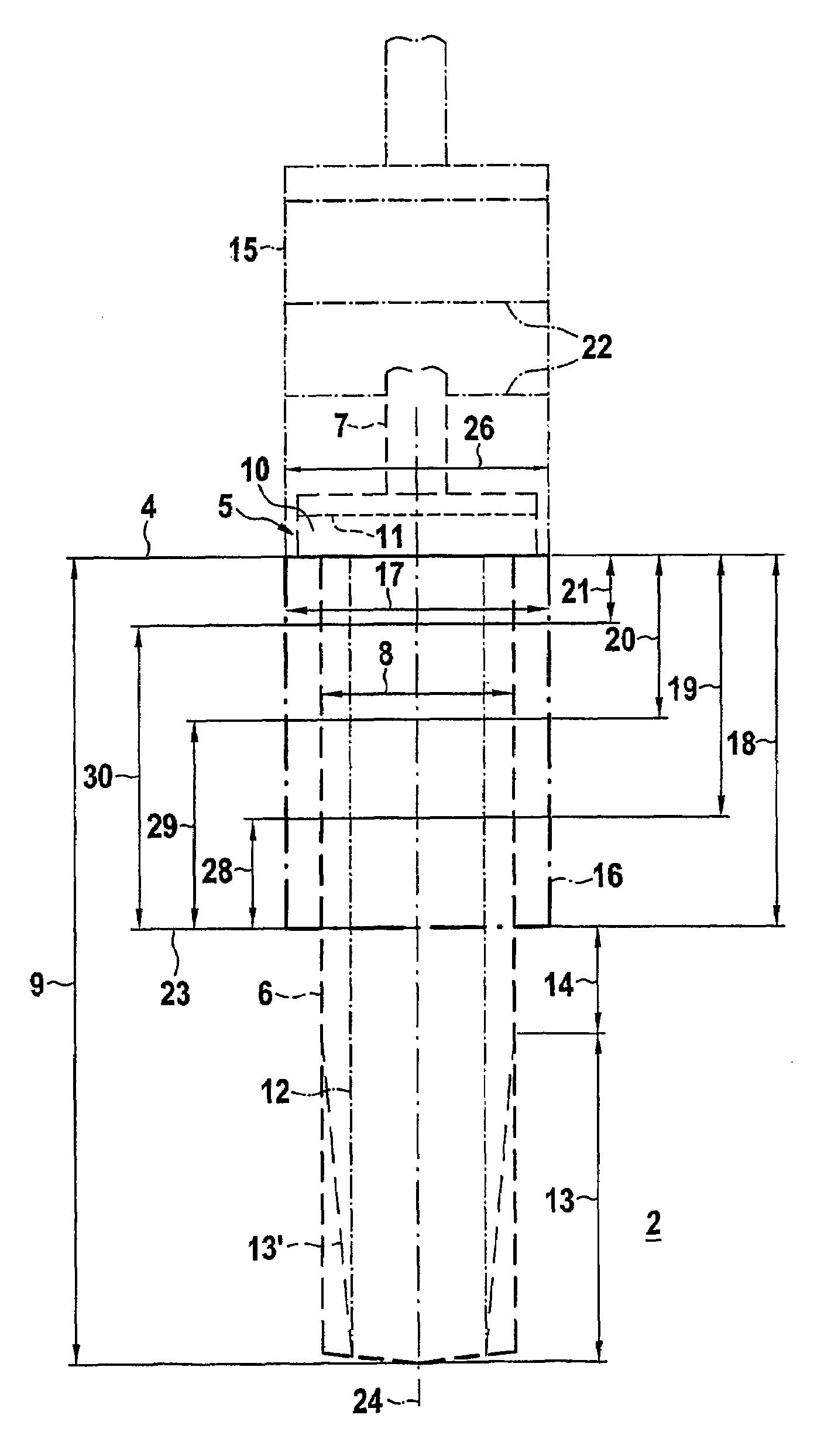
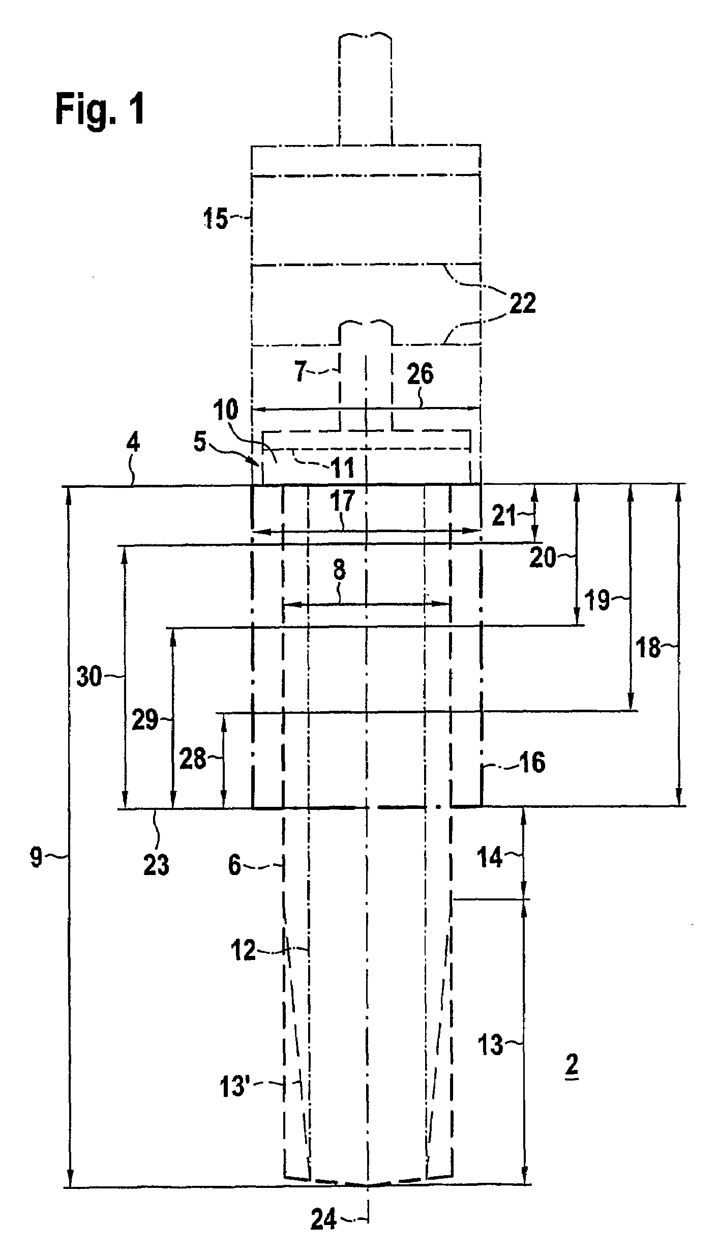
[0019]FIG. 1 diagrammatically shows a section through a bone 2 with an upper edge 4, in which a primary borehole 6 or a first drilling region, indicated by broken lines, is introduced by a primary drill 5. The primary drill 5, which is also shown by broken lines, contains a shaft, which can be inserted in a known manner in a drilling device. The primary borehole 6 or the first drilling region has a diameter 8 and a length 9, which is at least equal to the length of the implant, which is not shown here. Outside of the bone 2 or above the upper edge 4, the drill 5 has a stop or a radial expansion 10 and at least one marking 11, which form means for specifying the depth, of primary borehole 6. Furthermore, especially below the expansion 10, stop means can be provided for specifying or limiting the depth of introduction. Accordingly, boreholes, which are longer or deeper than the length 9 shown, can also be introduced with the same primary drill 5.

[0020]The primary drill 5 or the primar...


PUM


Abstract

The invention relates to an implant system containing at least one drill and one implant, particularly a dental implant, which can be screwed into a bore hole made in a bone by means of a drill. Preferably, the implant comprises a self-cutting screw with a thread core. The aim of the invention is to further develop an implant system which guarantees high primary stability for a wide variety of bone qualities and requires little technical complexity. According to the invention, the implant and the drill are co-ordinated in such a manner according to bone quality that a compressed zone arises when the implant is screwed into the implant in the bone. The size of the compressed zone is greater for low bone quality than for high bone quality.

Description

BACKGROUND OF THE INVENTION[0001]The invention relates to an implant system.[0002]An implant of this type is known, for example, from the U.S. Pat. No. 5,000,686. It is a dental implant with a self-cutting external thread. For inserting the implant, a borehole, the diameter of which corresponds essentially to the core diameter of the implant, is introduced into the jawbone-a drill. Subsequently, the implant is screwed into said borehole in the bone. In the case of the previously known implant, the core diameter of the thread, starting out from a cervical region, tapers towards an apical region, the depth of the thread being less in the cervical region than in the apical region. By these means, it is taken into account that the density of the bone is greater in the region of its upper edge than in lower lying areas. Classifications have therefore been proposed for different bone densities (qualities), for example, a classification of the alveolar bone into classes DI to DIV. The bone...

Claims


Application Information

Patent Timeline
IPC IPC(8): A61C8/00A61B17/16A61B17/86A61B90/00
CPCA61B17/863A61C8/0022A61C8/0024A61C8/0089A61B17/1615A61B2019/462A61C8/0045A61B2090/062
Inventor HAESSLER, DIETER
Owner FRIADENT
Why Eureka
Try Eureka