Mould, encapsulating device and method of encapsulation

Inactive Publication Date: 2007-05-01
BESI NETHERLANDS BV
View PDF13 Cites 5 Cited by
  • Summary
  • Abstract
  • Description
  • Claims
  • Application Information

AI Technical Summary

Benefits of technology

[0007]The invention provides for this purpose a mould. With such a mould a carrier can be placed on a simple way on the lower mould part and sucked against the lower mould part before closing of the mould. An important advantage over the prior art is that the carrier is easier to place on a bottom wall of the lower mould part than in an upper mould part. As of the number of apertures in the mould the carrier lies more or less flat against the lower mould part. The force of gravity thus co-acts with the suction through the runner, which makes it easier to position the carrier more or less flat. Thus is prevented that, when the mould is closed, electronic components and/or contact wires come into contact with a counter-mould part because the carrier is not flat. Especially where contact of components with the upper mould can occur, on positions oppos

Problems solved by technology

As the apparatus possesses only one sucking hole the apparatus is also not suited for placing a moun

Method used


Image

  • Mould, encapsulating device and method of encapsulation
  • Mould, encapsulating device and method of encapsulation

Examples


Embodiment Construction

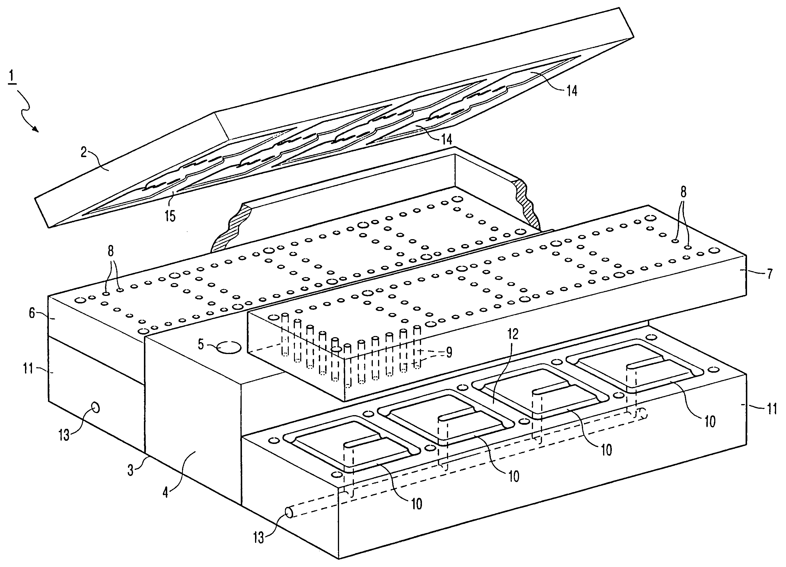
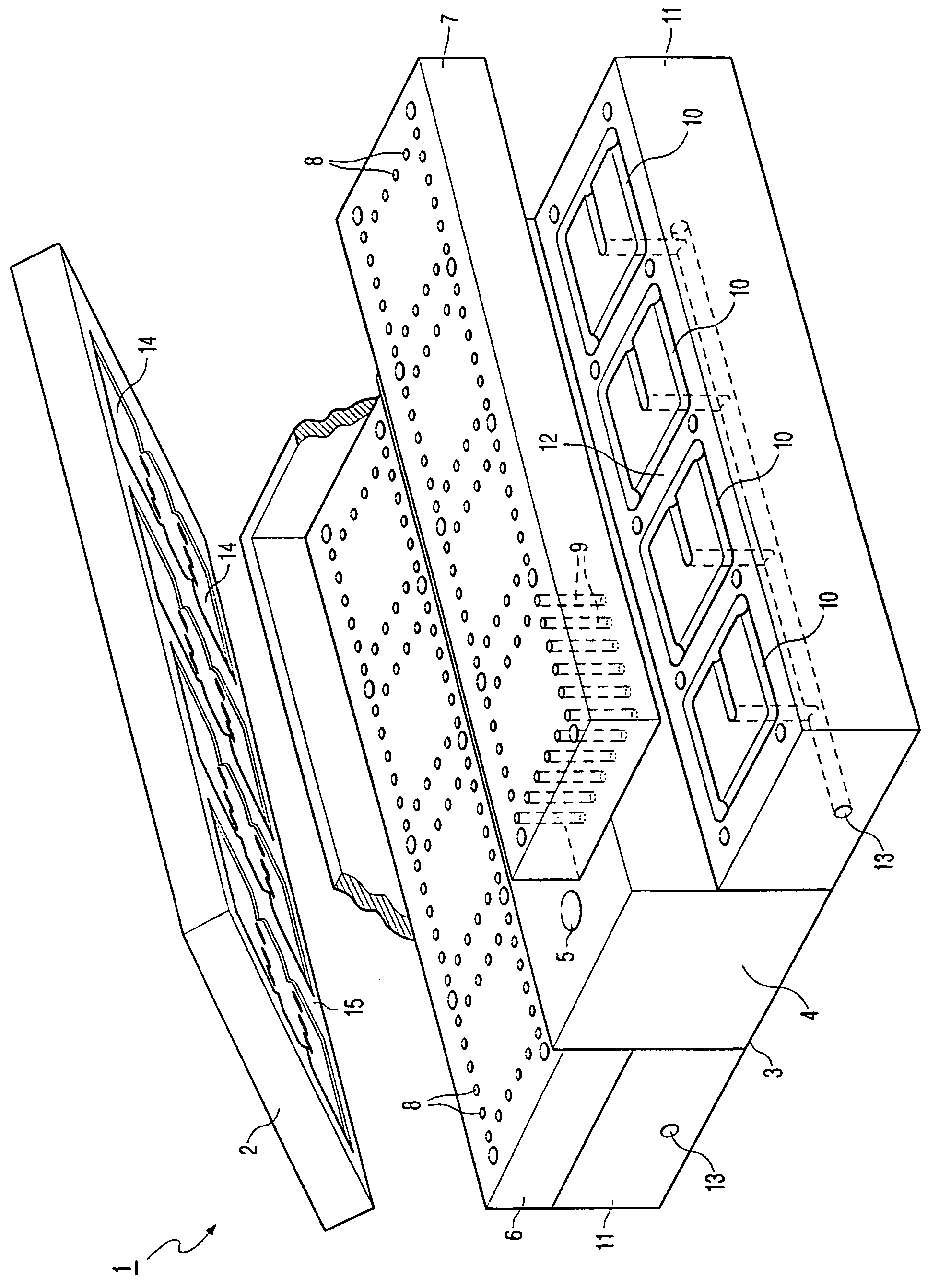
[0015]The FIGURE shows a mould 1 consisting of an upper mould part 2 and a lower mould part 3. Lower mould part 3 is provided with a central beam 4 in which recesses 5 are arranged for placing pellets of encapsulating material. Also situated in central beam 4 in each recess 5 are plungers (not shown) with which pressure can be applied to the encapsulating material.

[0016]Support plates 6,7 are arranged on either side of central beam 4. Support plate 7 is shown in a detached position while support plate 6 is shown in an assembled position. Support plates 6,7 are provided with a large number of apertures 8 which are placed together in groups. These apertures 8 connect onto runners 9 which run through support plates 6,7 and which are only shown for a few of the apertures 8 by means of broken lines. These runners 9 connect onto tracks 10 arranged in a base block 11. Base blocks 11 are adapted to bear support plates 6,7. Each base block 11 is provided with an internal bore 12 which connec...


PUM


Abstract

The invention relates to a mould for encapsulating electronic components mounted on a carrier, comprising: at least two mould parts displaceable relative to each other, at least one of which is provided with a recess, and feed means for encapsulating material, wherein at least one of the mould parts is provided with a runner which connects on one side to a wall of a mould part co-defining a mould cavity and connects on the other side to a side of the mould part remote from the mould cavity. The invention also relates to an encapsulating device of which such a mould forms parts, and to a method for encapsulating electronic components mounted on a carrier.

Description

BACKGROUND OF THE INVENTION[0001]The invention relates to a mould for encapsulating electronic components mounted on a carrier. The invention also relates to an encapsulating device. Finally, the invention also relates to a method for encapsulating components mounted on a carrier.[0002]Such a mould, encapsulating device and method form known art with which, using for instance epoxy resin, a package of encapsulating material can be applied round an electronic component arranged on a carrier. This technique is used particularly for encapsulating semiconductor products, such as for instance chips.[0003]1. Description of the Prior Art[0004]The European patent application EP 0 730 937 discloses a resin moulding machine with release film. The machine is provided with a mechanism that fixes release film on inner faces of the moulding sections and clamping faces. Also disclosed are air sucking holes in the upper die to hold substrates in the upper die. The loading of substrates in the machi...

Claims


Application Information

Patent Timeline
IPC IPC(8): B29C45/03B29C45/04B29C45/14H01L21/56
CPCH01L21/565H01L2924/0002H01L2924/00H01L21/56
Inventor TOMASSEN, MARCEL GERARDUS ANTONIUSCLAASSEN, ANTONIUS BERNARDUS
Owner BESI NETHERLANDS BV
Why Eureka
Try Eureka