Knob structure

Active Publication Date: 2007-05-01
MICRO-STAR INTERNATIONAL
View PDF8 Cites 17 Cited by
  • Summary
  • Abstract
  • Description
  • Claims
  • Application Information

AI Technical Summary

Benefits of technology

[0012]Accordingly, it is an object of the invention to provide a knob structure in which the rotary wheel may smoothly rotate on the body case in a manner of non-fixed engagement to reduce the number of defective products and alleviate the problem of the interference, so as to greatly enha

Problems solved by technology

On the other hand, if the number of the keys is small, though the volume of the MP3 player may be reduced, many operations will need to be performed by pressing two or three keys simultaneously, which complicates operation for the user.
Through the design of the touch knob, the iPod can not only perform various functions easily, but also has a reasonably small volume.
As such, the user may know whether the operation is performed through the physical tactility, so the buzzer demanded by the electronic touch knob is unnecessary.
Among the rotary component, the rotary wheel, the through-hole in the body case, and the body itself has dimensional errors,

Method used


Image

  • Knob structure
  • Knob structure
  • Knob structure

Examples


Embodiment Construction

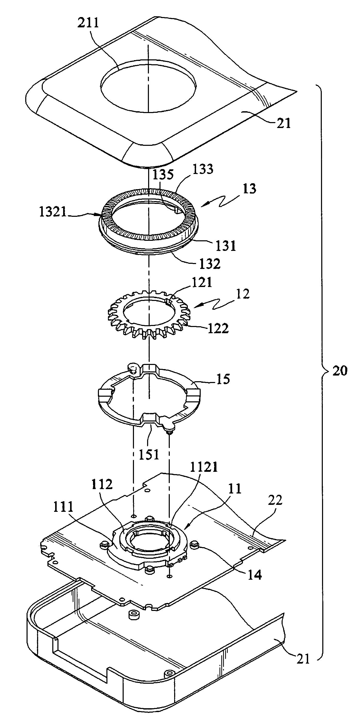
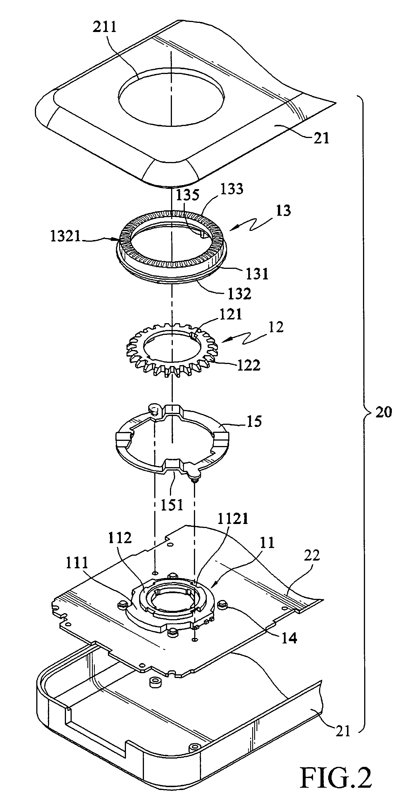
[0025]The knob structure disclosed by the present invention is disposed on an electronic device and used to input a preset control signal. The so-called control signal refers to the signal input into the electronic device to perform an action, such as enter, play, forward, backward, and sound volume control, according to a pulse signal generated by the knob structure, wherein the electronic device refers to an electronic data processing device, such as a mobile telephone, a PDA, a digital camera, a MP3 player, a MPEG4 player, a recording digital photo frame, and a handheld game player. In the following detailed illustration about the present invention, a knob structure applied in a MP3 player will be illustrated as one preferred embodiment of the present invention.

[0026]Referring to FIG. 2, a light emitting knob structure of the present invention is applied in an electronic device 20, wherein the electronic device 20 is a MP3 player. The electronic device 20 at least comprises a bod...


PUM


Abstract

A knob structure is disposed on an electronic device to input a preset control signal. The knob structure includes a rotary encoder, a brake wheel, and a rotary wheel. A plurality of ratchets is disposed around the circumference of the brake wheel and locked on the rotary encoder. The rotary wheel is rotatably disposed on the body case of the electronic device and is nested on the brake wheel correspondingly. A block is disposed on the rotary wheel to be embedded between the ratchets, so as to control the rotation of the rotary wheel to generate a preset control signal by causing the brake wheel to drive the rotary encoder to rotate. The rotary wheel and the brake wheel are engaged non-fixedly, so as to prevent the rotary wheel and the body case of the electronic device from interfering with each other.

Description

CROSS-REFERENCE TO RELATED APPLICATIONS[0001]This non-provisional application claims priority under 35 U.S.C. § 119(a) on Patent Application No(s). 094222562 filed in Taiwan, R.O.C. on Dec. 23, 2005, the entire contents of which are hereby incorporated by reference.BACKGROUND OF THE INVENTION[0002]1. Field of Invention[0003]The present invention relates to a knob structure, and particularly to a knob structure applied in an electronic device, wherein a preset control signal is input by rotating the knob structure.[0004]2. Related Art[0005]With the rapid popularity of multimedia technologies and applications, more and more types of portable electronic devices are appearing, such as mobile telephones, personal digital assistants (PDA), digital cameras, MP3 players, MPEG4 players, recording digital photo frames, and handheld game players. Further, with continuous advancement of science and technology, those portable electronic devices are becoming smaller in volume to be carried more c...

Claims


Application Information

Patent Timeline
IPC IPC(8): H01H19/00
CPCH01H19/005H01H19/025
Inventor WANG, CHIA-HOHU, CHING-SENCHIANG, CHI-YEN
Owner MICRO-STAR INTERNATIONAL
Why Eureka
Try Eureka