
Communication apparatus in radio network, transmission control method, threshold value control method, and radio network system

a technology of radio network and communication apparatus, applied in the field of communication apparatus in radio network, transmission control method, threshold value control method, radio network system, can solve the problems of excessive suppression of transmission in a radio link within a cell, large decrease in throughput, and failure to carry out transmission regulation between radio communication apparatuses. , to achieve the effect of high quality of radio line, excessive suppression of transmission, and better reception of signals

Inactive Publication Date: 2007-05-01
NEC CORP
View PDF10 Cites 4 Cited by
  • Summary
  • Abstract
  • Description
  • Claims
  • Application Information

AI Technical Summary

Benefits of technology

[0027]An objective of the invention is to provide communication apparatuses in radio networks, transmission control methods, threshold value control methods, programs, and radio network systems, which can avoid excessive transmission control on a radio link with small propagation loss and with high interference resistance.

Problems solved by technology

However, such transmission regulation is not carried out between radio communication apparatuses belonging to different cells.
Hence, when the communication apparatus shown in FIG. 7 is used for each radio communication apparatus employing the small zone scheme, transmission suppression frequently occurs in each communication apparatus, so that a large decrease in throughput arises.
However, even in that case, there is the problem that transmission is excessively suppressed in a radio link within a cell.
Hence, the problem is that transmission is excessively suppressed even in the radio link having a high interference resistance within cells.
However, the threshold value control method has the above-mentioned problem.
That is, even when a communication apparatus transmits signals via a radio link having a higher interference resistance, transmission is delayed if signals from communication apparatuses within the range are received.

Method used


Image

  • Communication apparatus in radio network, transmission control method, threshold value control method, and radio network system
  • Communication apparatus in radio network, transmission control method, threshold value control method, and radio network system
  • Communication apparatus in radio network, transmission control method, threshold value control method, and radio network system

Examples


Embodiment Construction

[0052]Embodiments of the present invention will be described in detail below with reference to the attached drawings.

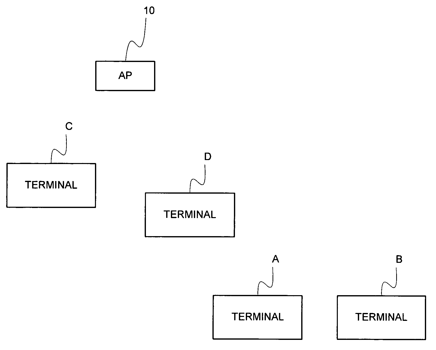
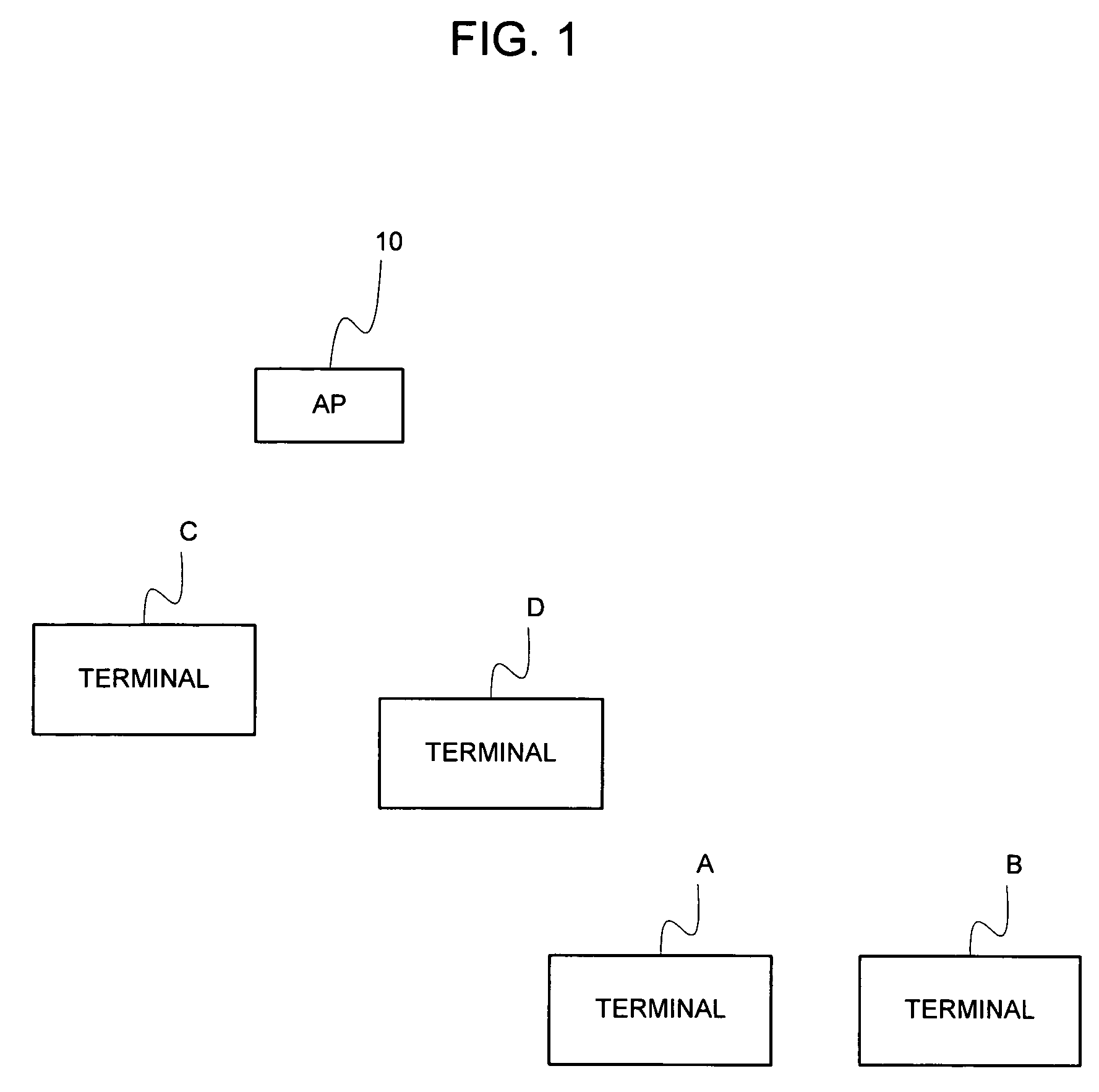
[0053]FIG. 1 is a diagram illustrating the configuration of a radio LAN (Local Area Network) system according to the first embodiment of the present invention. As shown in FIG. 1, the radio LAN system in the first embodiment includes an access point 10 and mobile terminals (mobile stations) A to D. In the first embodiment of the present invention, each of the mobile terminals A to D can communicate wirelessly with the access point 10 and with other mobile terminals via the access point 10.

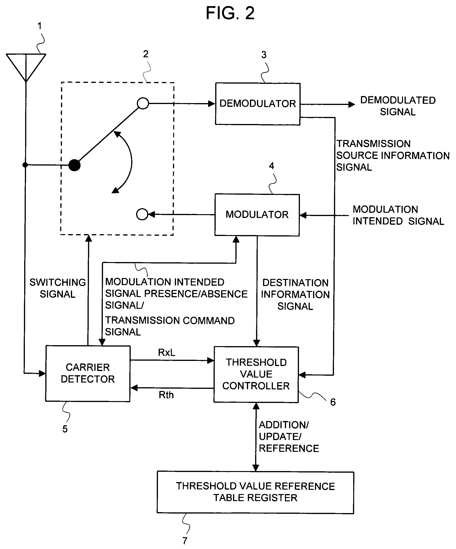
[0054]FIG. 2 is a diagram illustrating the configuration of the access point 10 shown in FIG. 1. As shown in FIG. 2, the access point 10 includes an antenna 1, a switch 2, a demodulator 3, a modulator 4, a carrier detector 5, a threshold value controller 6, and a threshold value reference table register 7. The switch 2, which is controlled by the carrier detector 5, selects the demod...


PUM


Abstract

The carrier detector 5 notifies the threshold value controller 6 of the received power value of a received signal and then controls various portions so as to defer transmission of the transmission signal when receiving a signal having a received power exceeding a threshold value Rth from the threshold value controller 6. The demodulator 3 notifies the threshold value controller 6 of a transmission source included in the received signal. The modulator 4 notifies the threshold value controller 6 of the destination of the transmission signal. The threshold value controller 6 outputs the received power value of a received signal from the destination, as a threshold value Rth, to the carrier detector 5.

Description

BACKGROUND OF THE INVENTION[0001]The present invention relates to communication apparatuses in radio networks, transmission control methods, threshold value control methods, programs, and radio network systems. Particularly, the present invention relates to communication apparatuses in radio networks, which defers transmission of transmission signals when signals, each having a received power exceeding a threshold value, are received.[0002]The CSMA (Carrier Sense Multiple Access) scheme is applied in the access control scheme for communication apparatuses in the radio LAN (Local Area Network), typified by the IEEE (Institute of Electrical and Electronics Engineers) 802.11 standard.[0003]Unlike the FDD scheme (Frequency Division Duplex scheme), the CSMA scheme utilizes the upstream line and the downstream line, with the same channel segregated. The significant concept of the CSMA scheme is that each communication apparatus performs carrier sensing (carrier detection). Transmission is...

Claims


Application Information

Patent Timeline
Patent Type & Authority Patents(United States)
IPC IPC(8): H04B1/44H04B17/345H04L12/28H04W24/08H04W28/08H04W52/24H04W72/08H04W74/08H04W84/12
CPCH04W28/08H04B17/318H04W52/24H04W72/08H04W28/10H04W72/54
Inventor FURUKAWA, HIROSHI
Owner NEC CORP
Learn More