Directional brain stimulation and recording leads

a brain stimulation and brain stimulation technology, applied in the field of brain stimulation and recording, to achieve the effect of effective localization of electrical stimulation, less interference, and improved sense ability

Inactive Publication Date: 2007-05-01
MEDTRONIC INC
View PDF78 Cites 204 Cited by
  • Summary
  • Abstract
  • Description
  • Claims
  • Application Information

AI Technical Summary

Benefits of technology

[0011]In addition, various embodiments of the present invention may have the object of improving the ability to sense and record electrical activity in localized regions of the b rain. For example, the present invention may address problems involving the recording of brain activity from small functional brain targets on a highly localized basis with less interference caused by activity in adjoining tissue within the brain. Accordingly, the present invention also may address problems involving the accuracy of recording signals from small functional brain targets.
[0012]The present invention has certain advantages. That is, in comparison to known implementations for delivering electrical stimulation to the brain, various embodiments of the present invention may provide one or more advantages. Such advantages may include, for example, more effective localization of electrical stimulation to very small brain targets, reduction of electrical stimulation of brain tissue adjoining a desired brain target, reduction in material side effects as a result of collateral stimulation of brain tissues adjoining a desired brain target, reduction in the need for lead tip repositioning relative to a desired brain target, flexibility in shaping and steering of electrical stimulation current emitted by a stimulation lead, flexible configuration and deployment of a stimulation lead as a function of the specific target characteristics identified by a surgeon, and ease of manufacture and cost effectiveness of stimulation leads providing any of the foregoing advantages.
[0013]As added advantages, various embodiments of the present invention may improve the ability to sense and record electrical activity in localized regions of the brain. For example, the present invention may be used to record brain activity from small functional brain targets on a highly localized basis with less interference caused by activity in adjoining tissue within the brain, contributing to increased accuracy in the recorded signals.

Problems solved by technology

Such problems may include, for example, delivery of electrical stimulation to desired targets within the brain with precision using deep brain stimulation leads, delivery of electrical stimulation to desired targets on a highly localized basis to the general exclusion of adjoining brain tissue, delivery of electrical stimulation to desired targets to thereby achieve a desired therapeutic response without causing undesirable side effects, and delivery of electrical stimulation to desired targets without the need for extensive repositioning of a deep brain stimulation lead.

Method used


Image

  • Directional brain stimulation and recording leads
  • Directional brain stimulation and recording leads
  • Directional brain stimulation and recording leads

Examples


first embodiment

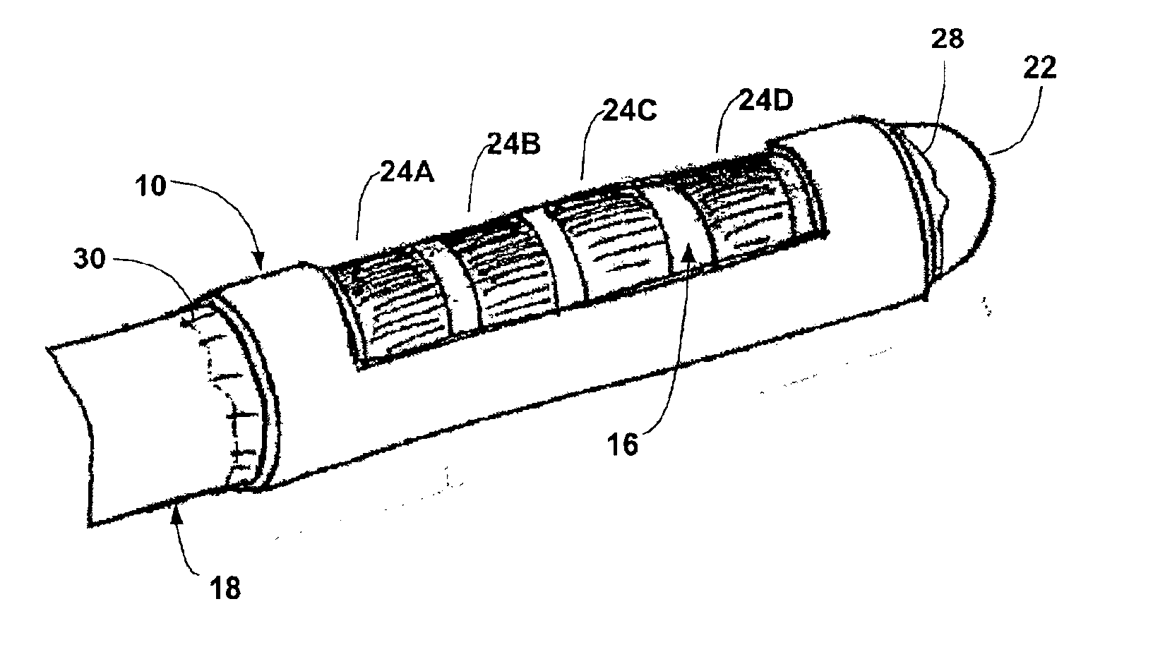
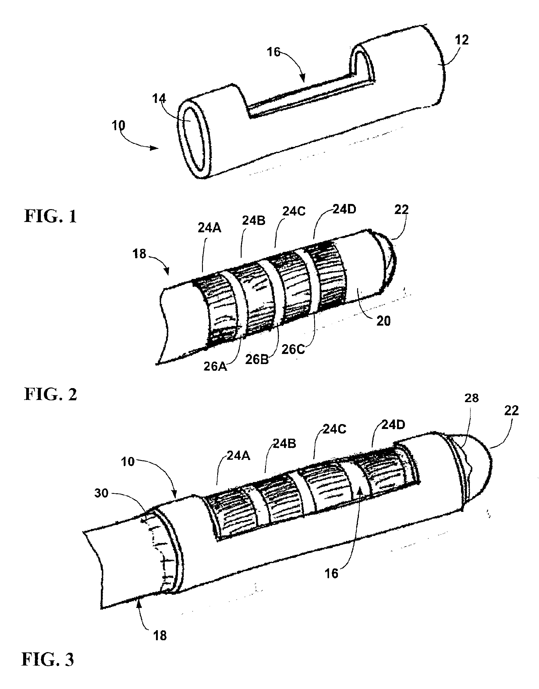
[0048]In the following detailed description of the preferred embodiments, reference is made to the accompanying drawings that form a part hereof, and in which are shown by way of illustration specific embodiments in which the invention may be practiced. It is to be understood that other embodiments may be utilized and structural or logical changes may be made without departing from the scope of the present invention. The following detailed description, therefore, is not to be taken in a limiting sense, and the scope of the present invention is defined by the appended claims. FIG. 1 is a perspective view of a windowed insulating member 10 for use with a deep brain stimulation lead in accordance with a As shown in FIG. 1, insulating member 10 has a substantially tubular body 12 defining an inner lumen 14 that extends axially along the length of the tubular body. Tubular body 12 also defines a window 16, i.e., an aperture, that permits access to inner lumen 14 from outside of the tubu...

second embodiment

[0063]FIG. 5 is a perspective view of a windowed insulating member in accordance with a As shown in FIG. 5, insulating member 34 is substantially cylindrical and has a tubular body 36 that defines an inner lumen 36. Insulating member 34 conforms substantially to insulating member 10 of FIG. 1, but includes two windows 40A, 40B formed at different positions along the length of insulating member 34. In particular, in the example of FIG. 4, windows 40A, 40B are formed at different axial positions along the length of insulating member 34, and on opposite sides of the insulating member. In this manner, insulating member 34 provides multiple windows at different axial and circumferential positions to provide the surgeon with greater flexibility in lead positioning.

[0064]FIG. 6 is perspective view illustrating a lead assembly incorporating the windowed insulating member 34 of FIG. 5 and the deep brain stimulation lead 18 of FIG. 2. As shown in FIG. 6, windows 40A, 40B expose different ele...

third embodiment

[0065]FIG. 7 is a perspective view of a windowed insulating member 42 in accordance with a As shown in FIG. 7, insulating member 42 is substantially cylindrical and has a tubular body 44 that defines an inner lumen 46. Insulating member 34 conforms substantially to insulating member 34 of FIG. 5, but includes four windows 48A, 48B, 48C, 48D (hereinafter 48) formed at different positions along the length of insulating member 42.

[0066]FIG. 8 is a perspective view illustrating a lead assembly incorporating the windowed insulating member 42 of FIG. 7 and the deep brain stimulation lead 18 of FIG. 2.

[0067]Windows 48A, 48C may be formed on one side of insulating member 42 in alignment with electrodes 24A, 24C. Similarly, windows 48B, 48D may be formed on an opposite side of insulating member 42 in alignment with electrodes 24B, 24D. Each window 48 of insulating member 42 exposes a portion of an individual electrode 24, to provide a directional capability that can be applied on an electro...


PUM


Abstract

A directional brain stimulation lead assembly provides a lead body and an insulating member defining one or more windows that selectively expose portions of electrodes carried by the lead body to produce a directional stimulation current field. The lead assembly can achieve more effective localization of electrical stimulation to very small brain targets, and thereby reduce the incidence of material side effects caused by collateral stimulation of brain tissue adjoining a desired brain target. In addition, the directional lead can sense brain activity on a more localized basis.

Description

[0001]This application claims priority from U.S. provisional application Ser. No. 60 / 254,281, filed Dec. 7, 2000, the entire content of which is incorporated herein by reference.FIELD OF THE INVENTION[0002]This invention relates to brain stimulation and recording and, more particularly, electrical leads useful in brain stimulation and recording.BACKGROUND OF THE INVENTION[0003]Deep brain stimulation (DBS) leads are used to stimulate nerve structures in specific areas of the brain to either excite or inhibit cell activity. A stimulation lead is implanted at a precise location within the brain using CT or MRI imaging techniques and stereotactic guidance. Once implanted, the stimulation lead delivers electrical stimulation to produce nerve impulses that inhibit symptoms of a brain disorder. For example, deep brain stimulation can be effective in the management of chronic pain of neuropathic and or nociceptive origin. In addition, deep brain stimulation can be used to treat movement dis...

Claims


Application Information

Patent Timeline
Patent Type & Authority Patents(United States)
IPC IPC(8): A61N1/05
CPCA61N1/0534A61N1/0531A61N1/36182
Inventor VAN VENROOIJ, PAULGIELEN, FRANS H.MULLETT, KEITH R.DUYSENS, VICTORGRUIA, DAN
Owner MEDTRONIC INC
Why Eureka
Try Eureka