
Power management apparatus, power management method, and power management system

Active Publication Date: 2007-05-01
FUJIFILM BUSINESS INNOVATION CORP
View PDF8 Cites 6 Cited by
  • Summary
  • Abstract
  • Description
  • Claims
  • Application Information

AI Technical Summary

Benefits of technology

[0010]Taking the above-described facts into consideration, an object of the present invention is to obtain a power management apparatus, a power management method, and a power management system that are each able to prevent an uncertain signal from being input to a device to which power is continually supplied from a device to which suppliance of power has been cut off when suppliance of power to an electric device switches from a power saving mode to a normal mode under conditions with a voltage insufficient to guarantee operation, thereby enabling an erroneous operation to be prevented.
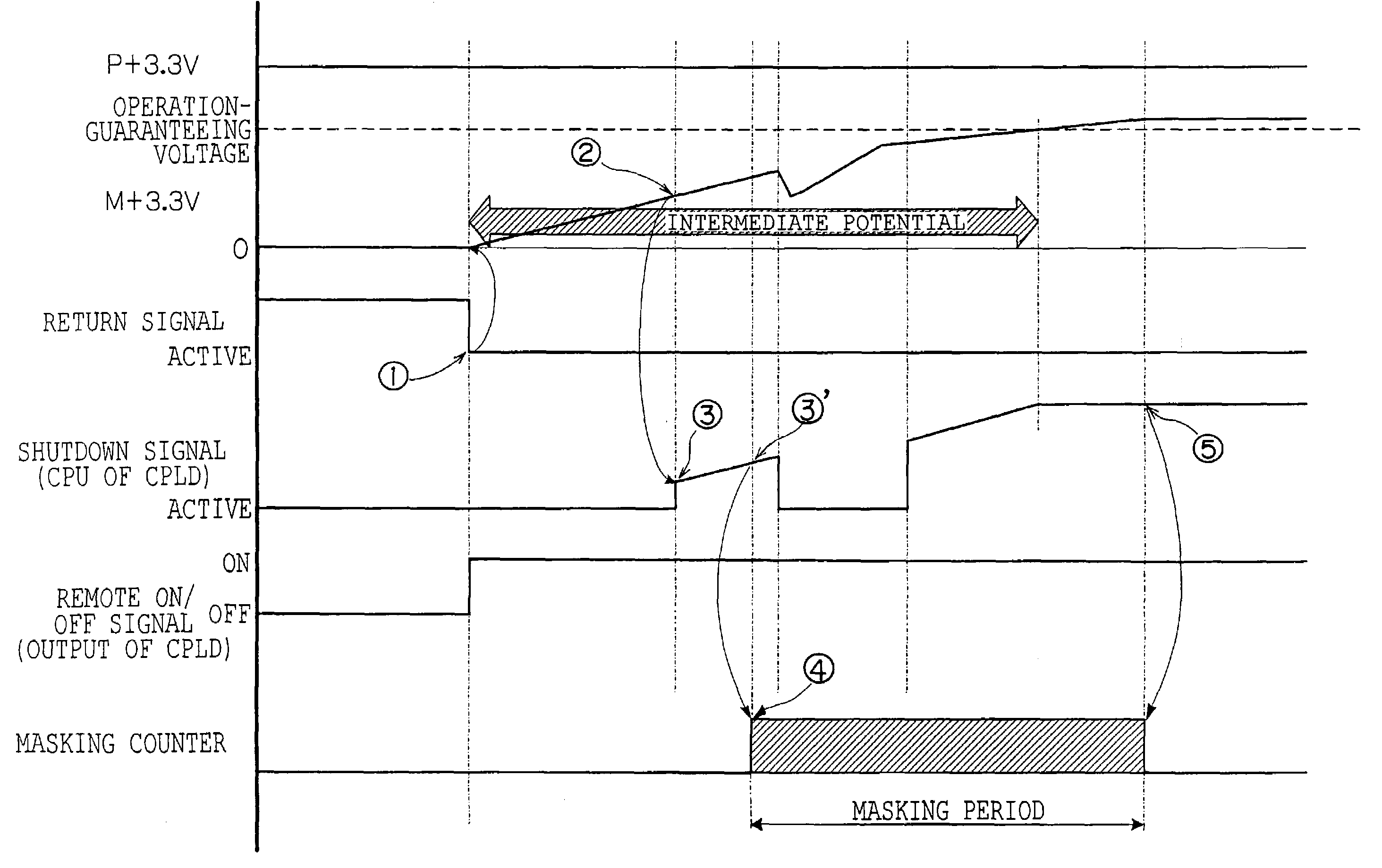
[0016]To avoid the problematic case, the masking component is provided to mask the uncertain signal using the input of the uncertain signal in the return operation as a trigger. Thereby, an erroneous operation can be prevented; and consequently, the return operation can stably be implemented.
[0020]According to the power management apparatus of the third aspect, the power management apparatus does not need to be controlled in the driving control circuit at the electric device side. Reduction in power consumption, which is an intrinsic purpose of the power saving mode, can be sufficiently exhibited.
[0022]According to the power management apparatus of the fourth aspect, in the power saving mode, it is sufficient to supply power only to the compact complex programmable logic device. Hence, the reduction in power consumption by the power saving mode can be efficiently implemented.
[0024]According to the power management apparatus of the fifth aspect, since a counter is used, while the device configuration is simple, the masking of the uncertain signal can be implemented.

Problems solved by technology

However, the continual suppliance of power in the power saving mode to the driving control circuit of the electrical device conflicts with an intrinsic purpose of the power saving mode for reducing power consumption.
This can cause a case, in which this device produces an uncertain signal.
A case can occur, in which the uncertain signal is input to a device, to which power is continually supplied even in the power saving mode, causing this device to operate erroneously.
In particular, when a shutdown signal is input to the CPLD because of the rush current, a case can occur, in which the return operation and shutdown operation are repeated, whereby the suppliance of power cannot be returned to the normal mode.

Method used


Image

  • Power management apparatus, power management method, and power management system
  • Power management apparatus, power management method, and power management system
  • Power management apparatus, power management method, and power management system

Examples


Embodiment Construction

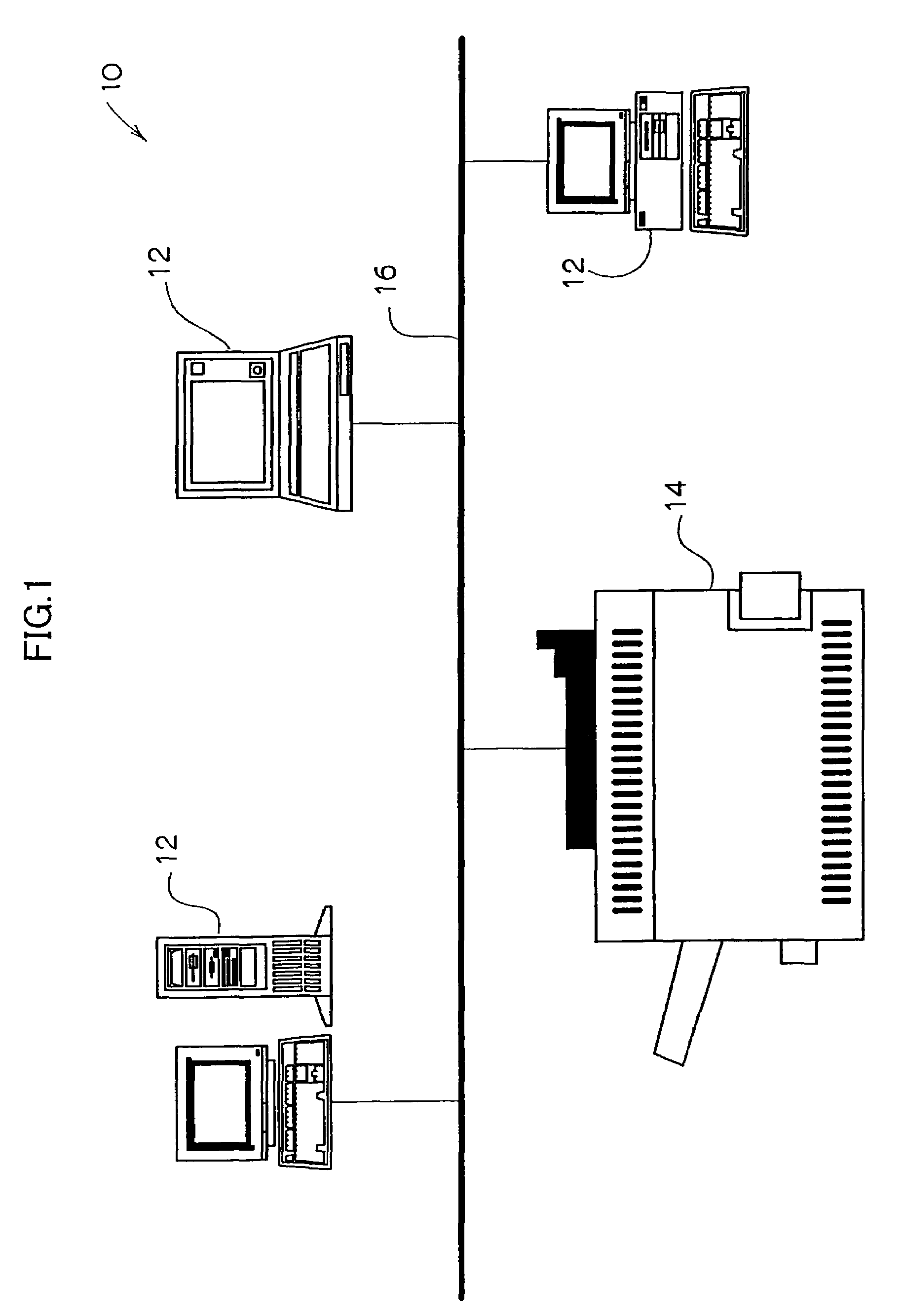
[0033]FIG. 1 shows a printer system 10 according to an embodiment of the present invention as a power management system in which printer control can be executed.

[0034]The printer system 10 includes a plurality of personal computers 12 (PCs) individually used as print-instructing apparatuses (instructing apparatuses) disposed on a plurality of desks at which individual users carry out work in an office. In addition, the printer system 10 includes a plurality of electric devices, specifically printers 14, distributed to individual sections in the office. The plurality of the PCs 12 and the plurality of printers 14 are connected via a network 16 such as a LAN (local area network).

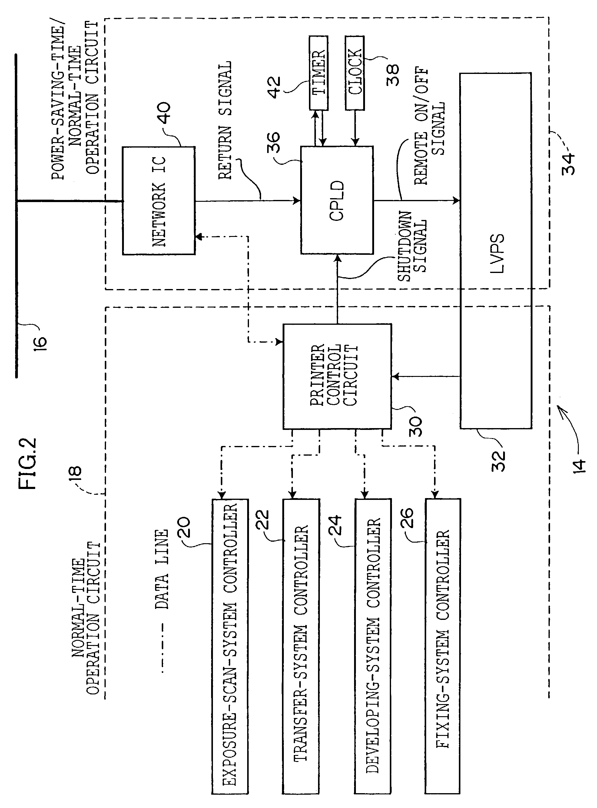
[0035]FIG. 2 shows a control block diagram of the printer 14.

[0036]A printer controller 18 is connected to an exposure-scan-system controller 20, a transfer-system controller 22, a developing-system controller 24, and a fixing-system controller 26 (these controllers will generically be referred to as control s...


PUM


Abstract

When causing a power saving mode to return by inputting a return signal, power is supplied to a device to which suppliance of power has been cut off. In this case, a power-saving control CPLD is masked to cancel an uncertain signal generated in the device under an intermediate potential at which the voltage of a power-saving-time power cutoff device, which supplies power to the device, is gradually rising. Thus, an erroneous operation caused by the uncertain signal can be prevented. Further, when the voltage of the power-saving-time power cutoff device reaches an operation-guaranteeing voltage, the power-saving control CPLD reads the uncertain signal again. Thereby, intrinsic characteristics of the uncertain signal can be verified, and a secure return operation can be implemented.

Description

BACKGROUND OF THE INVENTION[0001]1. Field of the Invention[0002]The present invention relates to a power management apparatus and a power management method for managing a power supply that supplies power to an electric device. In addition, the invention relates to a power management system including the power management apparatus.[0003]2. Description of Related Art[0004]Conventionally, a power management apparatus for supplying power to an electrical device has a function of automatically (or manually) switching to a power saving mode for suppliance of a minimal necessary power when the electrical device is inoperative for a predetermined time. Thereby, unnecessary power consumption is reduced, and consequently, resources can be conserved.[0005]When the electrical device is in the power saving mode, the suppliance of power can be returned to a normal mode using a return signal input according to a user's desire.[0006]In the conventional electrical device, even when the suppliance of...

Claims


Application Information

Patent Timeline
IPC IPC(8): G06F1/00B41J29/38G06F1/26G06F1/32G06F3/12
CPCG06F1/3209
Inventor OBARA, TAKENORIFUKUI, MEGUMIFUKUDA, YUKIHIRO
Owner FUJIFILM BUSINESS INNOVATION CORP
Learn More