Scissor lift mechanism

a technology of scissor lift and mechanism, which is applied in the direction of lifting frame, lifting device, building lift, etc., can solve the problems of hydraulic cylinders only having limited suitability in many practical applications, wear phenomena, and inability to apply force uniformly, so as to prevent any unintentional lowering of the lift mechanism

Active Publication Date: 2007-05-08
PRO HUB HEBETECHN
View PDF13 Cites 32 Cited by
  • Summary
  • Abstract
  • Description
  • Claims
  • Application Information

AI Technical Summary

Benefits of technology

[0023]It is particularly advantageous in this case if the guide element is constructed or designed as a damper or as an emergency brake in order to prevent any unintentional lowering of the lift mechanism when there is a sudden release of tension. In ordinary operation, use of a guide element which is equipped with a hydraulic cylinder, for example, makes possible a damping effect when the load changes.
[0024]The drive may be arranged in a fixed location spatially separate from the scissor lift mechanism. However, an especially compact embodiment can be achieved if the drive is mounted on the coupling bridge in a plane defined by the joint of the thrust struts and the swivel axis. Several drives may be provided arranged opposite each other so that one is associated with each coupling bridge.

Problems solved by technology

It has proven to be a disadvantage with such scissor lift mechanisms that their height of lift is varied by an expansion body; that the lever ratios in the lowered resting position vary greatly from those in the raised working position.
In practice, this results in wear phenomena.
However, this means a large opening path of the hydraulic cylinder, so that here again, the forces required to be applied may vary greatly.
Furthermore, hydraulic cylinders have only a limited suitability in many practical applications because of the oil they release.
However, it is a disadvantage here that this results in two speed levels in the lifting and lowering operations and that a jerky change in speed occurs when the expansion body is gripped by a supporting swivel arm.
Precise positioning is therefore no longer possible in the transition area.

Method used


Image

  • Scissor lift mechanism
  • Scissor lift mechanism
  • Scissor lift mechanism

Examples


Embodiment Construction

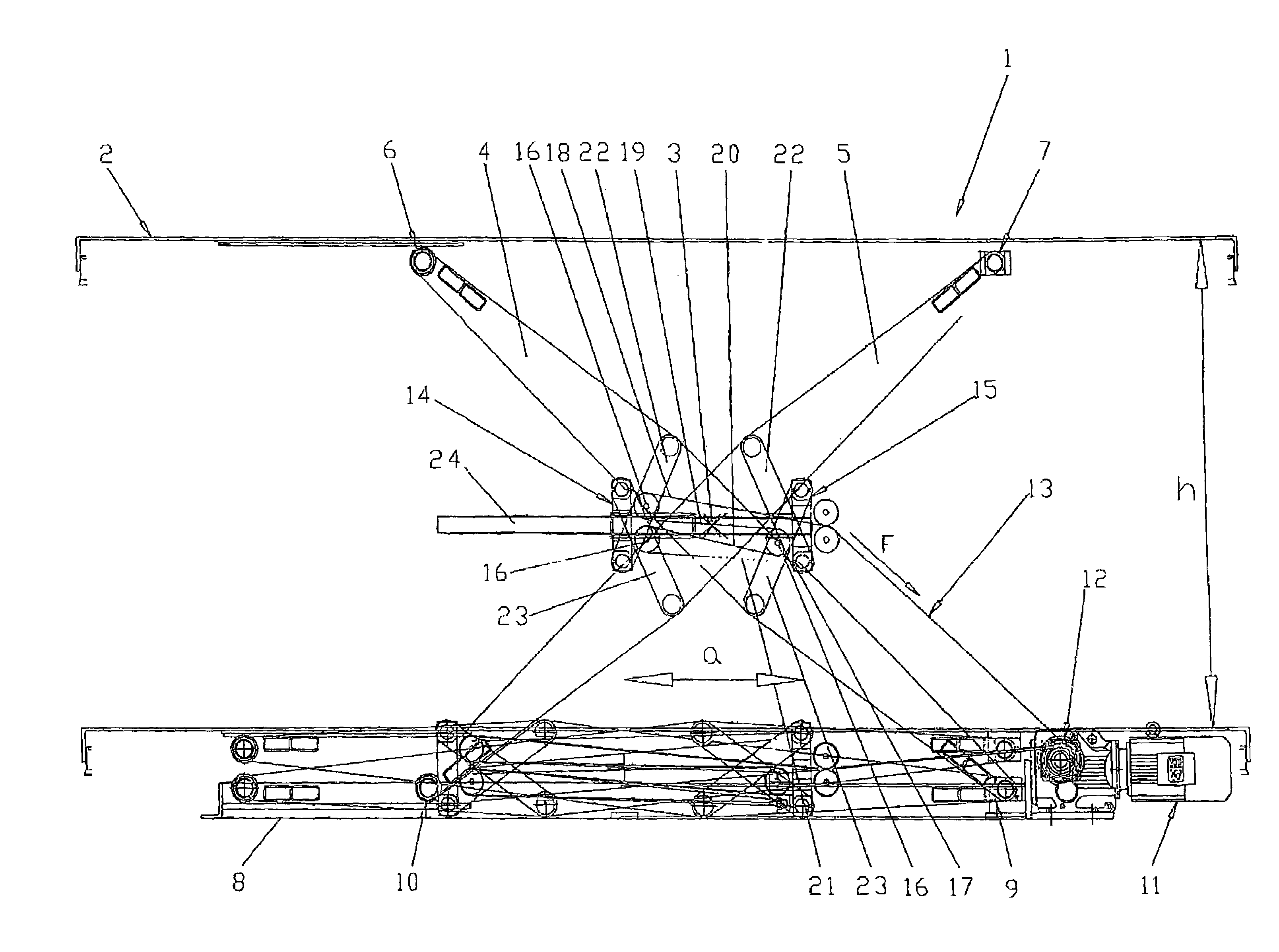
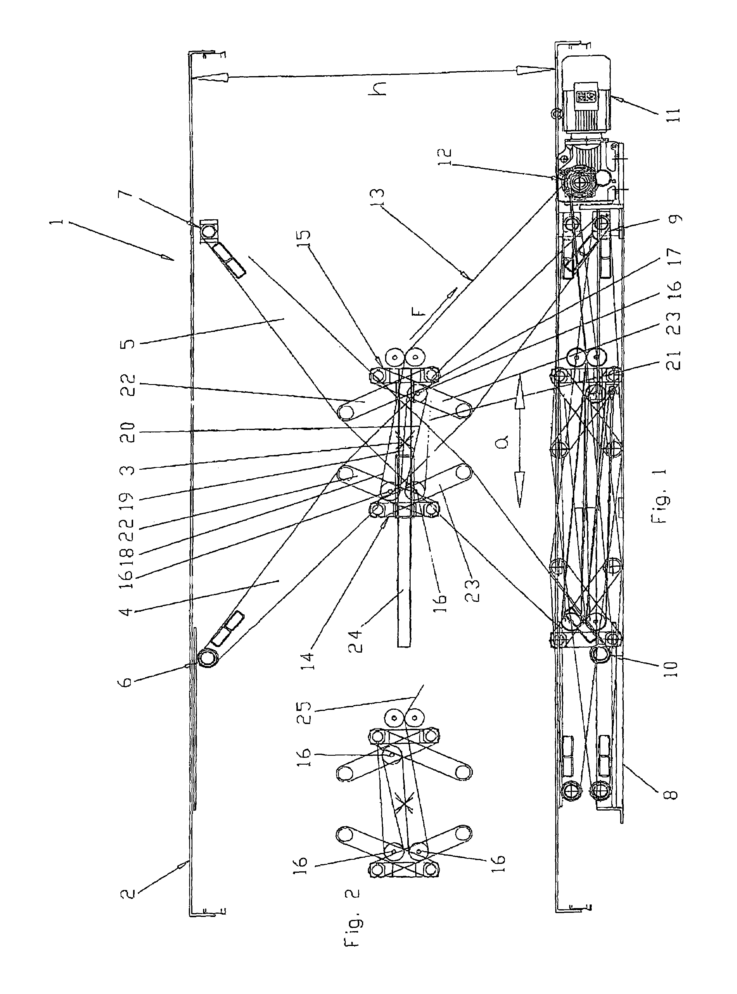
[0030]FIG. 1 shows a side view of a scissor lift mechanism 1 according to the invention. The scissor lift mechanism 1 has two scissor elements 4, 5 which are located beneath a lifting surface 2 and are connected in pairs by a swivel axis 3, whereby swivel axis 3 is arranged in the middle between the end sections 6, 7 of the scissor elements 4, 5 supporting the lifting plane 2 on the one hand and end sections 9, 10 which rest on a base surface 8 on the other hand. The scissor lift mechanism 1 is further equipped with a drive 11 in a stationary mount on the base surface 8. A traction member 13 in the of form a preferably flat belt for raising and lowering the scissor 4, 5 is provided on the winding drum 12 of the drive 11. To this end the scissor lift mechanism 1 is equipped with two parallel coupling bridges 14, 15 arranged on both sides of the swivel axis 3, the first coupling bridge 14 being equipped with at least two reversing rollers or pulleys 16 and the second coupling bridge 1...


PUM


Abstract

A scissor lift mechanism (1) having at least two scissor elements (4, 5) connected in pairs by a swivel axis (3). The drive (11) for raising and lowering the scissor elements (4, 5) is provided by a traction member (13). To reduce the driving power required for operation while at the same time reducing control complexity, the scissor lift mechanism (1) is equipped with two coupling bridges (14, 15) situated on opposite sides of the swivel axis (3) and pivotably supported by thrust struts (22, 23) on each of the two scissor elements (4, 5), respectively. The distance “a” between the coupling bridges (14, 15) and the resulting height of lift “h” are easily variable by applying a tractive force “F” via the traction member (13, 25) which is guided around reversing rollers (16) and back and forth along a plurality of generally parallel paths (18, 19, 20, 21) between the two coupling bridges (14, 15).

Description

BACKGROUND OF THE INVENTION[0001]This invention relates to a scissor lift mechanism having at least two scissor elements connected in pairs by a swivel axis, so that the swivel axis is arranged between the respective end sections of the scissor elements; and having a drive for raising and lowering the scissor elements by a traction member.[0002]A scissor lift mechanism of this type is described, for example, in published German Patent application no. DE 100 24 075 A1. Through the traction member, the distance between the upper and lower ends of the scissor elements is varied. The traction member is therefore connected to one end of one scissor element and to the drive via a pulley on an upper end of the other scissor element and therefore it can be drawn in. In this case, the traction member acts on an expansion body which in the lowered resting position of the scissor lift mechanism is situated close to the lower end of a scissor element between it and the upper end of the other sc...

Claims


Application Information

Patent Timeline
Patent Type & Authority Patents(United States)
IPC IPC(8): B66B11/06B66F7/06
CPCB66F7/065
Inventor KAUFMAN, MICHAEL
Owner PRO HUB HEBETECHN
Why Eureka
Try Eureka