
Push button release mechanism for supplemental tailgates

a tailgate and push button technology, applied in the field of vehicle tailgates, can solve the problems of unnecessarily complicating the tailgate release mechanism, affecting the attractiveness of the vehicle, and inconvenient for the operator to reach, so as to achieve convenient use, low manufacturing cost, and convenient maintenance.

Active Publication Date: 2007-05-08
FORD GLOBAL TECH LLC +1
View PDF2 Cites 14 Cited by
  • Summary
  • Abstract
  • Description
  • Claims
  • Application Information

AI Technical Summary

Benefits of technology

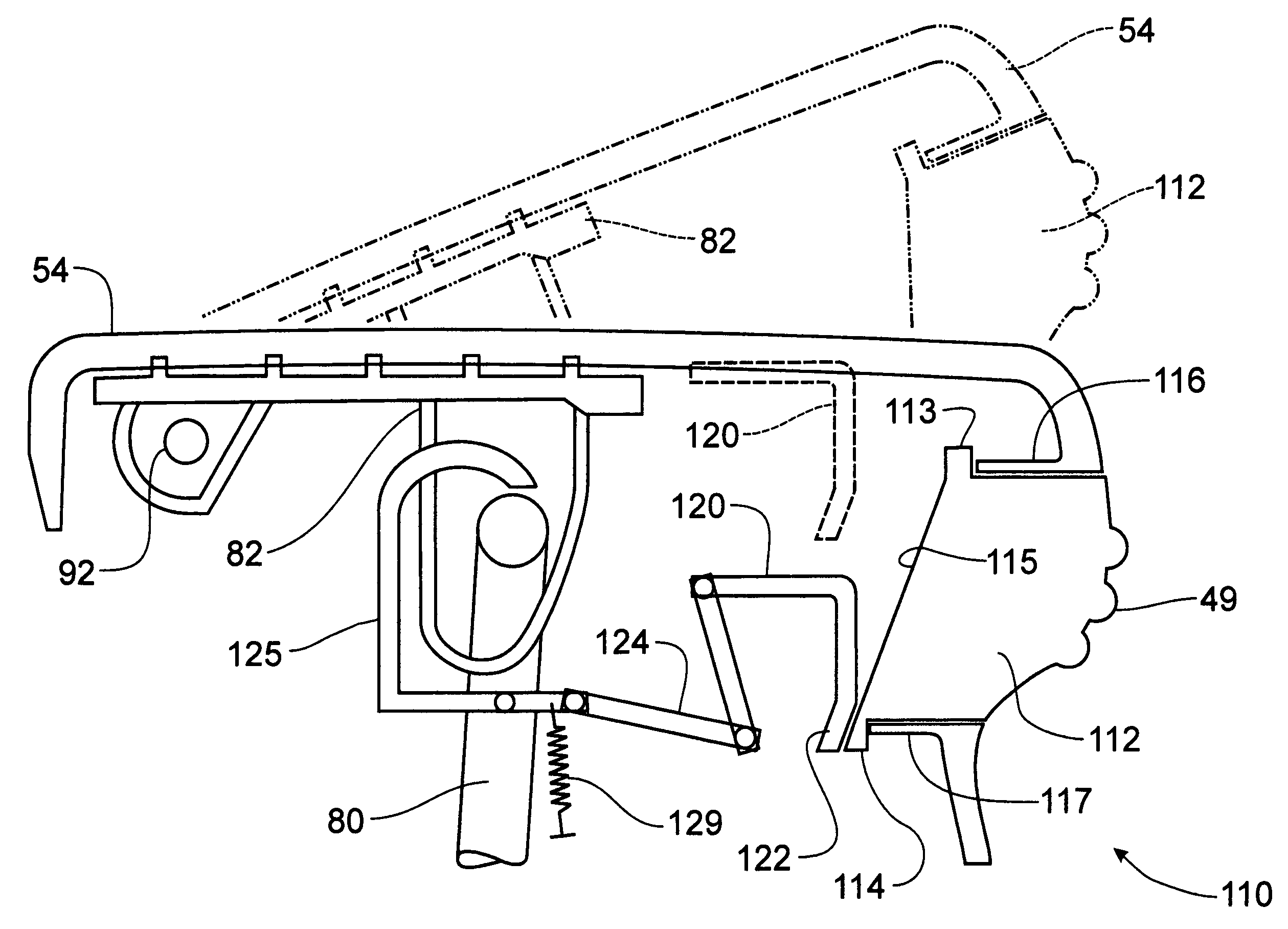
[0008]An advantage of an embodiment of the present invention is that a portion of the tailgate molding can be employed to operate as a supplemental tailgate release handle while also avoiding paint scratch concerns on the top surface of the tailgate. This avoids the need for a separate supplemental tailgate release handle assembly and molding, thus reducing the number of parts in the tailgate assembly, reducing the overall costs, and reducing the overall package space within the tailgate needed to perform both functions. Avoiding a separate supplemental tailgate release handle by having the supplemental tailgate release built into the pivotable portion of the tailgate molding has another advantage—the tooling that is used to produce many of the metal parts for the conventional tailgates may also be used for the same metal parts on the tailgates that include the supplemental tailgate.
[0016]It is a another object of this invention to provide a push button release mechanism for a supplemental tailgate mechanism that is durable in construction, inexpensive of manufacture, carefree of maintenance, facile in assemblage, and simple and effective in use.

Problems solved by technology

Being out of sight when not in use presents a more attractive vehicle, but these designs also require a separate handle to disengage latching mechanisms, which can be very inconvenient for the operator to reach and unnecessarily complicate the tailgate release mechanisms.
Other designs for bed extenders mount to the outside of the tailgate, which may be convenient for deployment and avoid concerns with deployment mechanisms, but they tend to interfere with cargo space in the box since the bed extender, when not in use, protrudes into the box.
Moreover, it is typical for the vehicle operator to employ the extender only occasionally, so it is undesirable to have the extender exposed at all times, which detracts from the attractiveness of the vehicle.
Another drawback with common bed extenders is that a desirable feature of conventional tailgates may be lost.

Method used


Image

  • Push button release mechanism for supplemental tailgates
  • Push button release mechanism for supplemental tailgates
  • Push button release mechanism for supplemental tailgates

Examples


first embodiment

[0061]Referring now to FIGS. 16–17, a push button release mechanism 110 for the supplemental tailgate apparatus 22 can best be seen. The push button release mechanism 110 is cooperable with the pivotable molding 54 to prevent an inadvertent movement of the molding 54 from releasing the supplemental tailgate apparatus 22 from its stowed position within the tailgate 20. the push button release mechanism 110 utilizes the shape of the pivotable molding 54 as substantially depicted in FIG. 14 and forms a push button 112 at the handle beads 49. The push button 112 is preferably formed as a cored out plastic block and is slidably positioned in the molding 54 between an upper channel flange 116 and a lower channel flange 117 that guide the push button 112 in a linear path of movement.

[0062]The push button 112 is preferably formed with an upper stop member 113 and a lower stop member 114. The lower stop member 114 hangs below the level of the lower channel flange 117 and engages the lower ch...

third embodiment

[0069]FIG. 21 is a push button release mechanism 150 in which the push button 152 depresses into the molding structure 54, but is connected directly to the actuation lever 147 to effect pivotal movement of the catch member 145 for deployment of the supplemental tailgate structure 22. In this embodiment, the molding 54 would not pivot, but would be fixed to the supplemental tailgate structure 22 for deployment therewith. In operation, the push button 152 would be depressed into the tailgate structure 20 to cause a pivotal movement of the catch member 145 and enable the supplemental tailgate apparatus 22 to be pulled out of the tailgate structure 20. The torsion spring 139 will return the push button 152 out of the tailgate 20 via the direct connection of the actuation lever 147 to the push button 152. One skilled in the art will recognize that the catch mechanism 145 would be adapted to re-engage automatically the supplemental tailgate apparatus 22 when returned to the stowed positio...


PUM


Abstract

A one hand push button release mechanism is associated with a supplemental tailgate assembly to affect the release of the supplemental tailgate for deployment from the main tailgate apparatus. One embodiment of the push button mechanism engages a wedge having a cam surface that causes the wedge to move vertically with respect to the push button to pull on a linkage that releases a pivoted catch member. A second embodiment utilizes a laterally slidable push button that depresses into the molding to engage a spacer that is laterally movable with the push button to be movable into an interfering position with respect to the catch member to lock the supplemental tailgate in the stowed position. In both embodiments, a spring is operable to bias the locking mechanism into a locked position when the supplemental tailgate is returned to the stored position.

Description

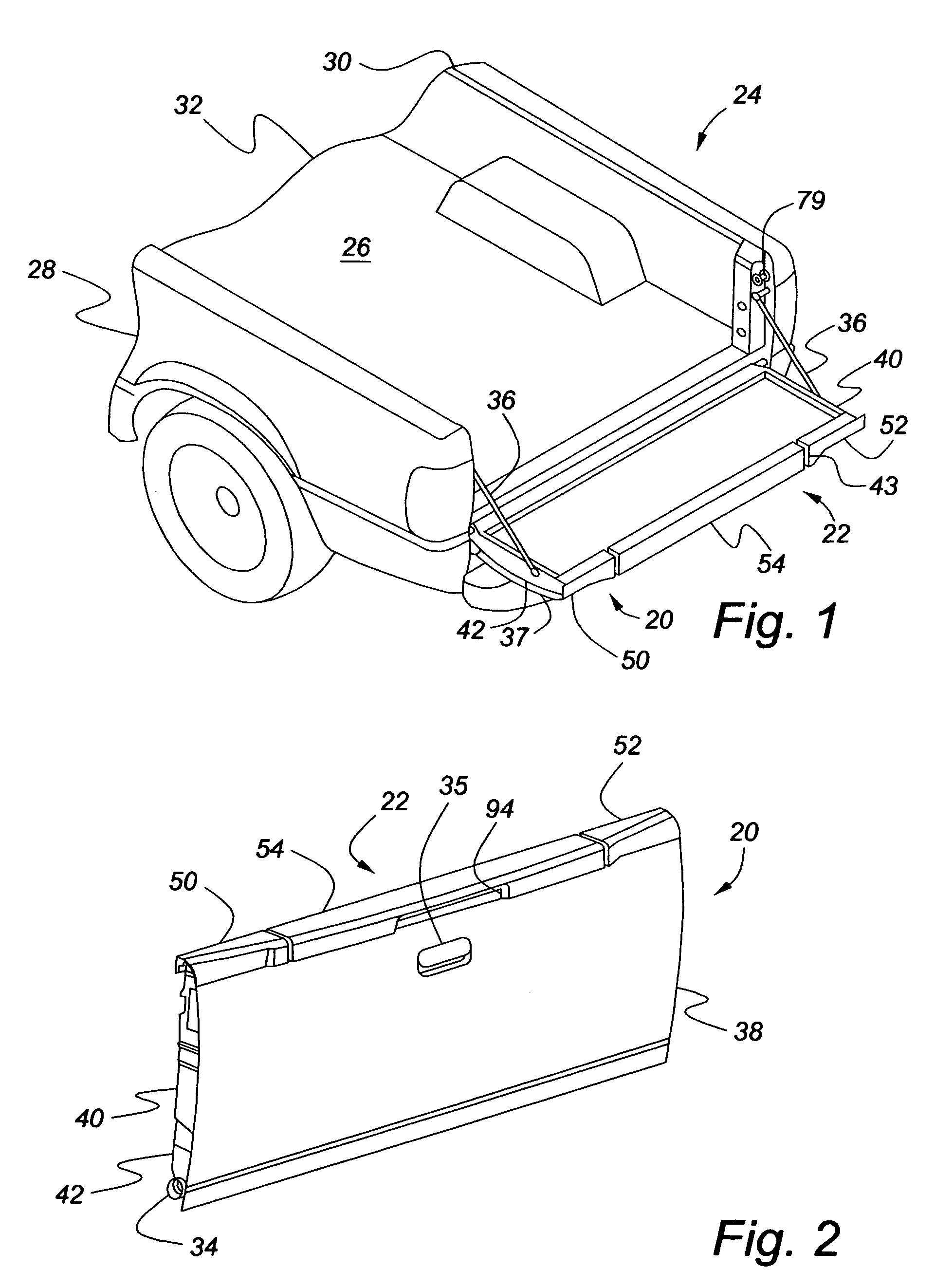
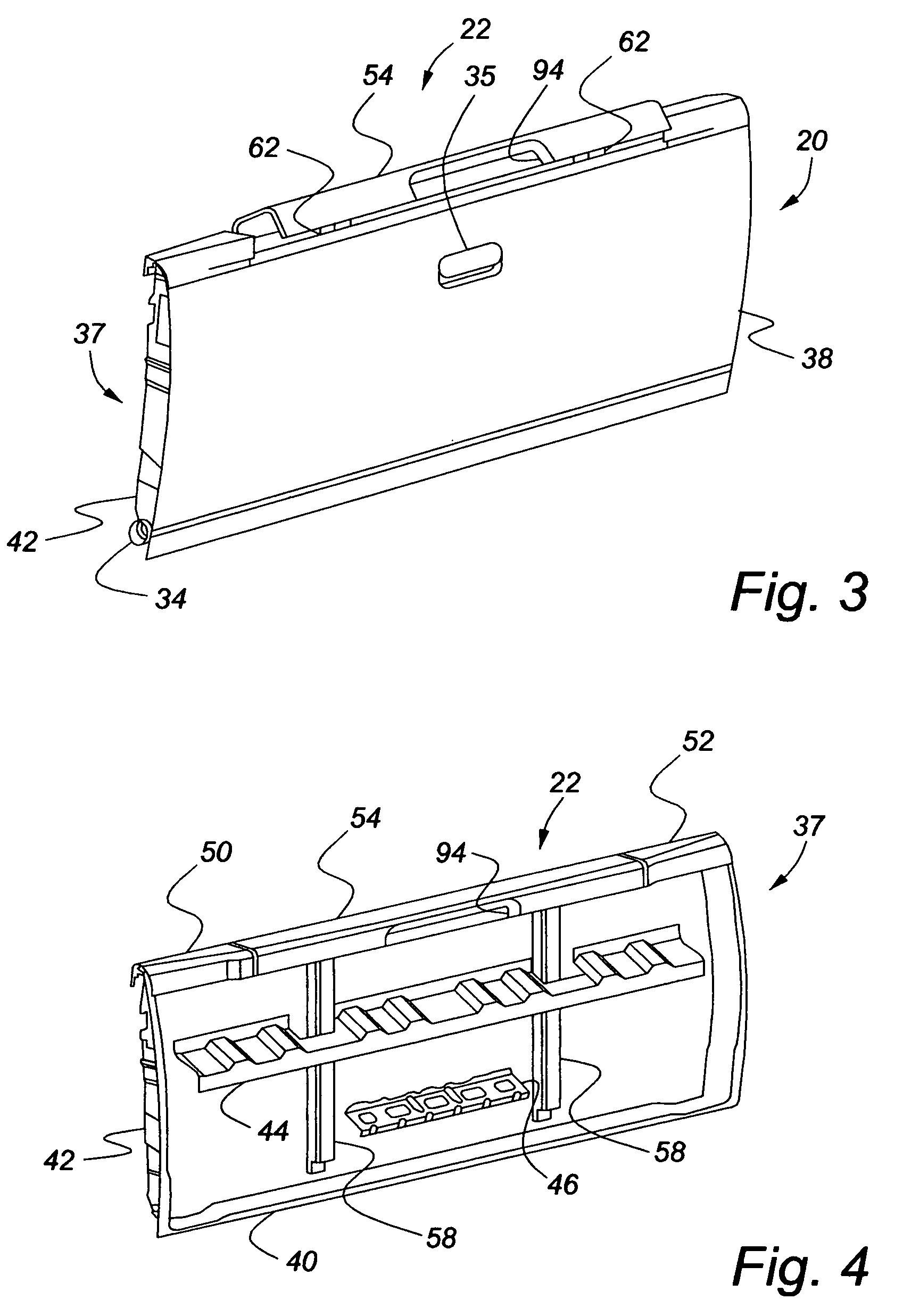
BACKGROUND OF THE INVENTION[0001]The present invention relates to vehicle tailgates that include a multifunction assembly extendable therefrom, and, more particularly, to a push button release mechanism to facilitate the utilization of the supplemental tailgate mechanism.[0002]Conventionally, pickup trucks include a tailgate at the back of a bed that closes off a cargo box. Often times, the truck bed is not long enough to hold the cargo, so truck bed extenders have been developed. The truck bed extenders work in conjunction with the tailgate in order to provide additional length to the bed. Some designs for pickup truck bed extenders have flush mounted extenders that are stowed in the tailgate when not in use. Being out of sight when not in use presents a more attractive vehicle, but these designs also require a separate handle to disengage latching mechanisms, which can be very inconvenient for the operator to reach and unnecessarily complicate the tailgate release mechanisms. Othe...

Claims


Application Information

Patent Timeline
Patent Type & Authority Patents(United States)
IPC IPC(8): B62D33/03
CPCB62D33/0273B62D33/037
Inventor TAN, KIAN-HUATMILLER, SCOTTCHENG, ALDOUSHOWELL, ROBERT
Owner FORD GLOBAL TECH LLC
Learn More