Steering handle for outboard motor

a technology for outboard motors and steering handles, which is applied in the direction of waterborne vessels, marine propulsion, vessel construction, etc., can solve problems such as lead wire twisting

Active Publication Date: 2007-05-08
YAMAHA MARINE KK
View PDF8 Cites 28 Cited by
  • Summary
  • Abstract
  • Description
  • Claims
  • Application Information

AI Technical Summary

Problems solved by technology

Unfortunately, if a speed control switch is mounted on the rotatable grip of a steering handle, the low speed control switch and the grip rotate together causing twisting of a lead wire connected to the low speed control switch.
The twisting of the lead wire can cause wear.

Method used


Image

  • Steering handle for outboard motor
  • Steering handle for outboard motor
  • Steering handle for outboard motor

Examples


Embodiment Construction

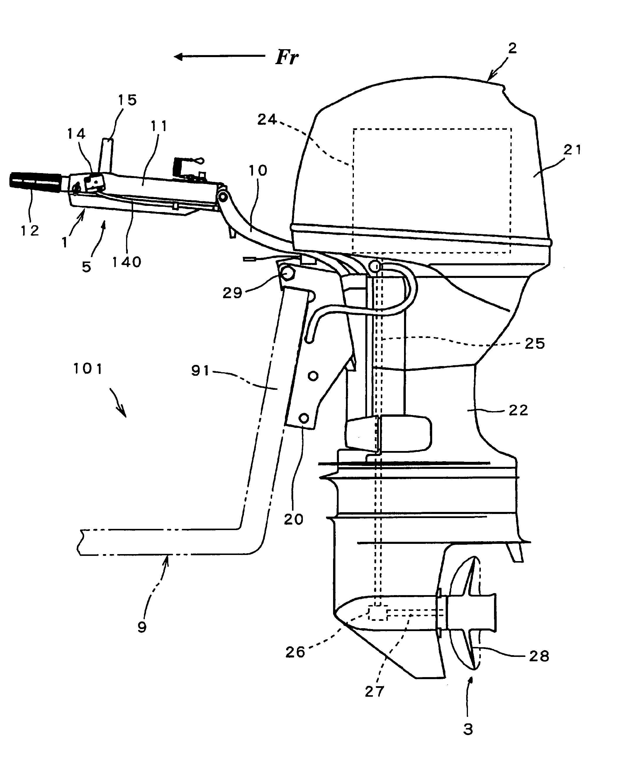
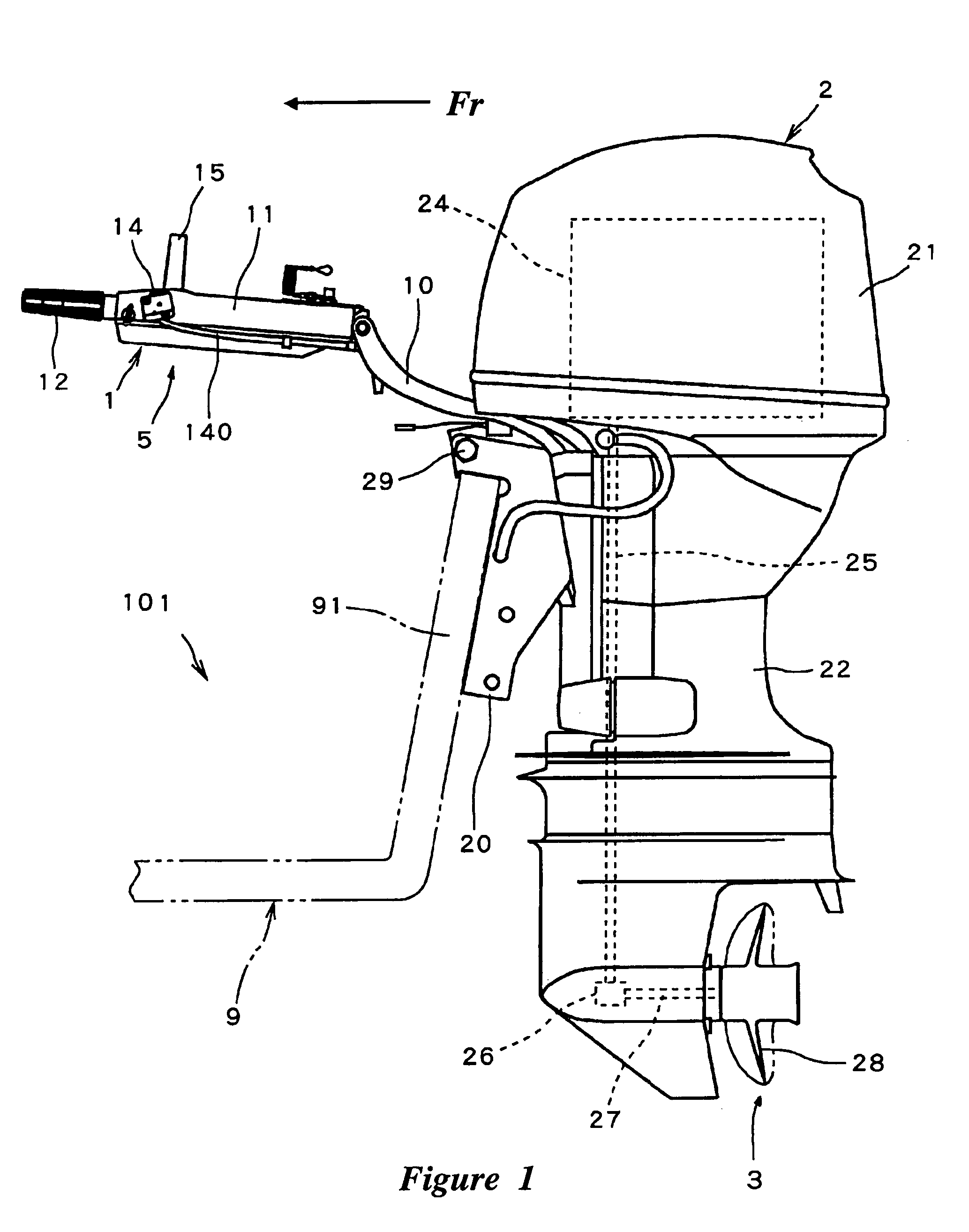
[0021]FIG. 1 is a side view showing the overall construction of an outboard motor 2 having a steering handle assembly 5.

[0022]A watercraft 101 has a hull 9 that carries the outboard motor 2, which has a propulsion unit 3 and an internal combustion engine 24 (shown in phantom). The engine 24 of the outboard motor 2 powers the propulsion unit 3. The illustrated propulsion unit 3 is a single propeller system; however, other types of propulsion units can be used as well, such as, for example, a dual counter-rotational propeller system, a jet drive, and the like. The outboard motor 2 is supported on a transom plate 91 of the hull 9 by a clamp bracket 20 so as to place at least a portion of the propulsion unit 9 in a submerged position when the watercraft 101 rests in the water.

[0023]The outboard motor 2 is preferably steerable and / or tiltable by moving the clamp 20. The arrow FR in the drawing indicates the forward direction in which the watercraft 101 travels. The terms “proximal” and “...


PUM


Abstract

A steering handle assembly for an outboard motor has a low speed control switch with at least one lead wire that is not twisted during control of the watercraft. The low speed control switch provides precise control of the engine speed of the outboard motor. The steering handle assembly has a handle with an elongated handle body. The handle body is connected to the outboard motor. A grip is rotatably mounted to a distal end of the handle body and is rotatable about the axis of the handle body.

Description

PRIORITY CASES[0001]The present application is based on and claims priority under 35 U.S.C. § 119(a–d) to Japanese Patent Application No. 2004-139264, filed on May 7, 2004, the entire contents of which is expressly incorporated by reference herein.BACKGROUND OF THE INVENTIONS[0002]1. Field of the Inventions[0003]The invention relates to a steering handle assembly for operating an outboard motor of watercraft and, more particularly, to a steering handle assembly having a low speed control switch for controlling the engine speed of the outboard motor.[0004]2. Description of the Related Art[0005]Watercraft vehicles, such as boats, are often powered by an outboard motor having an internal combustion engine. The outboard motor can be attached to the aft end of a hull of a watercraft. A steering handle can extend from the outboard motor. The handle is used to steer and control the engine speed of the outboard motor. The steering handle can include a handle body and a rotatable grip. The g...

Claims


Application Information

Patent Timeline
Patent Type & Authority Patents(United States)
IPC IPC(8): B60W10/04B63H5/125B63H20/12B63H21/22
CPCB63H20/12B63H21/213
Inventor KOJIMA, AKIKO
Owner YAMAHA MARINE KK
Why Eureka
Try Eureka