Illuminated disconnecting handle for use with CDM

a technology of electric circuit and disconnecting handle, which is applied in the direction of circuit-breaking switch details, protection switch operating/release mechanisms, switching device condition indication, etc., can solve the problems of difficult to determine the cause of failure using the above described assembly, difficult to hear the noise of the closed cabinet, and difficult to solve the solution. not very useful, so as to reduce the amount of labor required and reduce the cost

Active Publication Date: 2007-05-08
ROCKWELL AUTOMATION TECH
View PDF23 Cites 26 Cited by
  • Summary
  • Abstract
  • Description
  • Claims
  • Application Information

AI Technical Summary

Benefits of technology

[0022]It has also been recognized that one or more lights can be provided as integral parts of a handle assembly thereby reducing the costs associated with assemblies that require both a handle and one or more lights as well as reducing the amount of labor required to assemble the assembly. In at least some embodiments, where lights are provided as part of the handle assembly, electricity can be provided to the lights through the same door opening through which the handle extends to link to the disconnect means.

Problems solved by technology

Unfortunately, while the above described assembly facilitates relatively safe breaker operation, the assembly has several shortcomings.
First, when assembly components fail, it is relatively difficult to determine the cause of failure using the above described assembly.
Unfortunately this solution is not very useful as audible noise from the closed cabinet is often difficult to ascribe to the various components mounted therein when the door is closed.
While some failures result in easily observable damage to components, in many cases failures do not cause visually recognizable damage.
For instance, in some cases normally open power contactor contacts may stick or fuse closed and the fused contacts may not be positioned in any easy to observe orientation or, the source of the sticking may not be readily visually observable.
In other cases additional relay contacts may be stuck in abnormal transitional states.
While processes that provide power to power contactors and to the power contactor coil while the cabinet door is open are known, clearly these processes are relatively hazardous due to power flow and therefore should be avoided whenever possible.
Second, the assembly described above requires many parts, requires a good deal of time and labor to configure and therefore is relatively expensive.
As another instance, after lights are mounted to door 20, wiring has to be run form the lights to the associated auxiliary contacts and power source which increases configuration costs and time considerably.
Third, in most cases breaker assemblies cannot be easily modified to alter assembly functionality.
Fourth, when separate components are provided on door 20 to facilitate control and to indicate assembly states, the front face of the door becomes excessively crowded and cumbersome to use.

Method used


Image

  • Illuminated disconnecting handle for use with CDM
  • Illuminated disconnecting handle for use with CDM
  • Illuminated disconnecting handle for use with CDM

Examples


Embodiment Construction

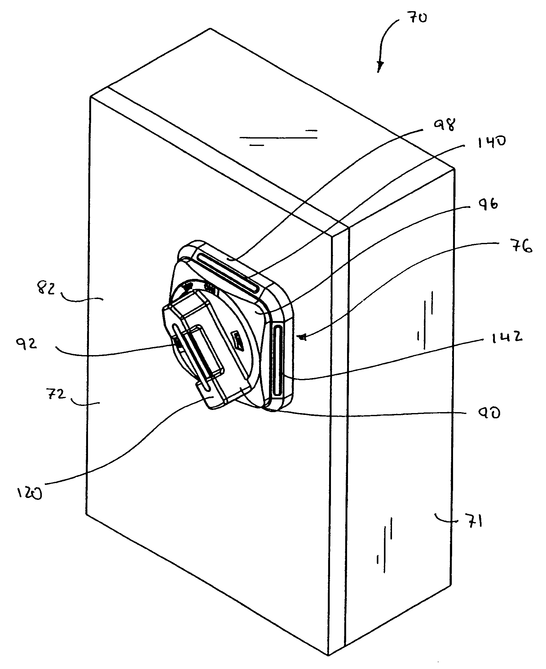
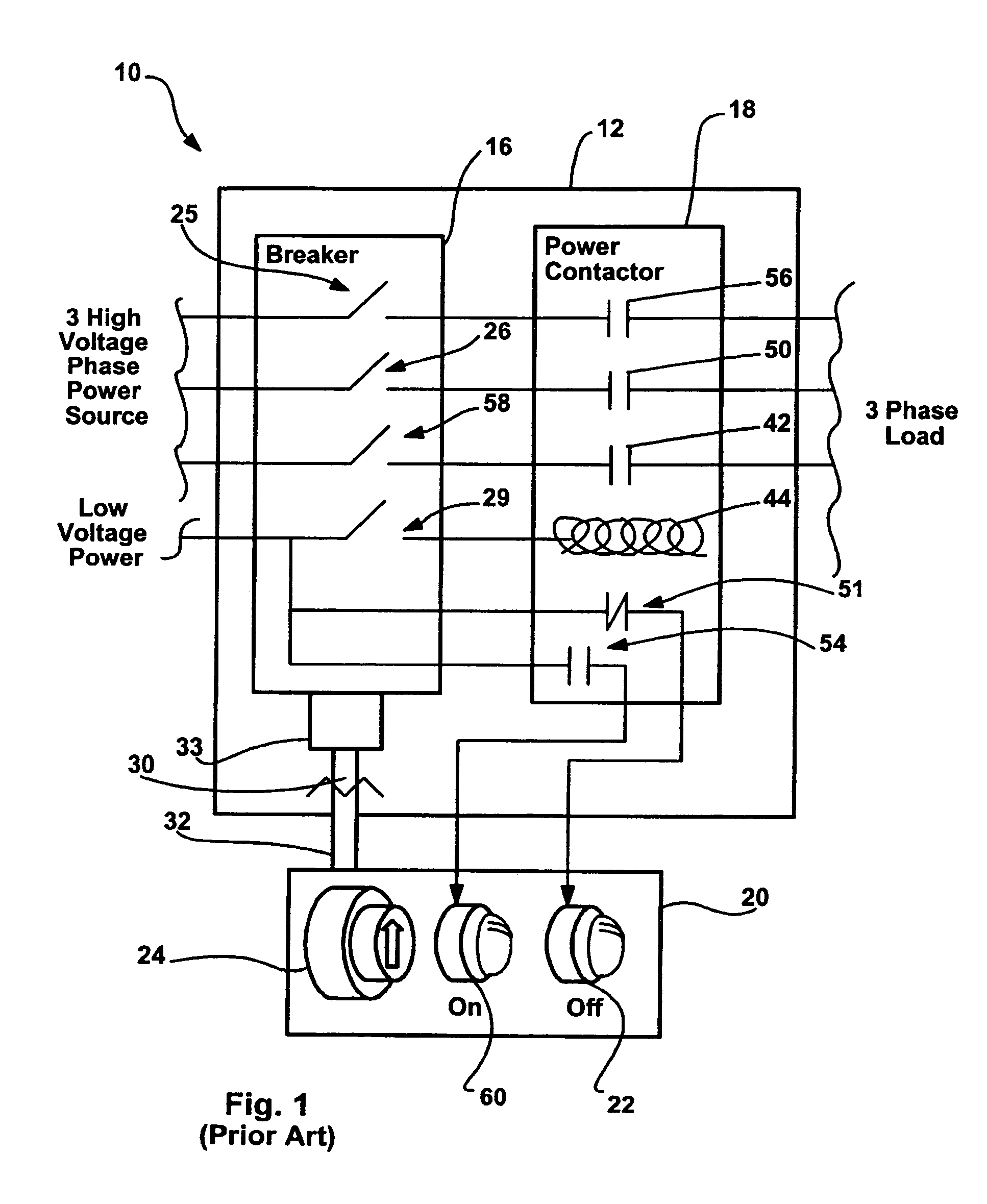
[0043]Referring now to the drawings wherein like reference numerals correspond to similar elements throughout the several views and, more specifically, referring to FIGS. 3 and 4, the present invention will be described in the context of an exemplary breaker block 70 including a rigid metallic cabinet 71, a cabinet door 72, a breaker assembly 78, a mechanical disconnect assembly 99 and an inventive handle assembly identified generally by numeral 76. Cabinet 71 is a rectilinear box including a back wall 74 opposite an open front face. Referring also to FIG. 14, three-phase power is provided to cabinet 71 via three supply lines (not labeled) and three supply lines exit cabinet 71 and are linked to a load. Breaker assembly 78, as illustrated in FIG. 15, includes a three-phase circuit breaker 416 and a power contactor 418 that are similar to the breaker and contactor described above with respect to FIG. 1. In FIG. 15, breaker 416 includes three breaker switches 425, 426 and 458 while po...


PUM


Abstract

An apparatus for use with a control assembly including a power source and a circuit disconnector located on a first side of a planar member forming an opening, the disconnector including a first mechanical linkage having open and closed positions, the apparatus for manipulating the mechanical linkage between the open and closed positions and visually indicating on a second side of the planar member at least a first state of the control assembly when the first state occurs, the apparatus including a handle assembly including a handle member moveable between at least first and second positions and positioned on the second side of the planar member adjacent the opening, an extension member rigidly connected to and extending from the handle member through the opening and forming a second mechanical linkage at a distal end that is linkable with the first mechanical linkage on the first side of the planar member, the extension member moving the first mechanical linkage between the closed and open positions when the handle is moved between the first and second positions, respectively and at least a first light emitter positioned on the second side of the planar member, and at least a first contact linkable between the power source and the first light emitter that closes to provide power to the first light emitter when the first state occurs.

Description

CROSS-REFERENCE TO RELATED APPLICATIONS[0001]Not applicable.STATEMENT REGARDING FEDERALLY SPONSORED RESEARCH OR DEVELOPMENT[0002]Not applicable.BACKGROUND OF THE INVENTION[0003]The present invention relates to electrical circuit disconnecting means (CDM) for mounting in cabinets and having a forwardly-extending, rotary disconnect that engages a handle on a cabinet door when the cabinet door is closed, and in particular, to an improvement in such CDM that provide visual indications of assembly states outside the cabinet as well as provide auxiliary contacts within the cabinet that are controllable irrespective of the position of the door.[0004]Hereinafter, unless indicated otherwise and in order to simplify this explanation, the present invention will be described in the context of a breaker assembly that includes a circuit breaker. Nevertheless, it should be appreciated that the concepts described herein are also applicable to other types of CDM including fusible disconnects, non-fu...

Claims


Application Information

Patent Timeline
Patent Type & Authority Patents(United States)
IPC IPC(8): H01H9/00H01H27/00
CPCH01H71/04H01H71/46H01H9/0066H01H9/162H01H11/0006H01H73/14
Inventor HOUCK, III, THEODORE J.BATTANI, JEFFREY JOHN
Owner ROCKWELL AUTOMATION TECH
Why Eureka
Try Eureka