
Method in frequency converter provided with voltage intermediate circuit, and frequency converter

a technology of voltage intermediate circuit and frequency converter, which is applied in the direction of dynamo-electric converter control, electric generator control, duplex signal operation, etc., can solve the problems of generator delay, inconvenient operation, and inconvenient operation, so as to reduce the amount of effective power to be transferred

Active Publication Date: 2007-05-08
ABB (SCHWEIZ) AG
View PDF11 Cites 16 Cited by
  • Summary
  • Abstract
  • Description
  • Claims
  • Application Information

AI Technical Summary

Benefits of technology

[0008]The invention is based on controlling the power to be transferred to the network to a predetermined value using a frequency converter. This value may be zero when interference is detected in the network to be supplied. Thanks to this control procedure, the amount of effective power to be transferred can be reduced for the duration of network interference. Even though the transfer of effective power were stopped altogether, reactive power could still be transferred. For this reason, the frequency converter modulates continuously and thus remains synchronized with the generator and the network. After network recovery, the transfer of effective power can be started immediately. Thus the advantages of the invention are achievable by using a frequency converter according to the invention.

Problems solved by technology

Such a solution is not, however, cost effective since the connecting and disconnecting are slow procedures, requiring re-start of the whole system.
Earlier, the rise in the intermediate circuit voltage has been limited employing various brake choppers or crowbar arrangements, where the produced power is used in resistor resistances.
A disadvantage associated with such solutions is that if it has been necessary to end the modulation of the frequency converter, the generator start-up and synchronization cause a generator delay.
The ending of modulation results in a loss of accurate information on the electric state of the generator and network, and consequently, when the network normalizes, the frequency converter has to synchronize with the generator and the network to be supplied.

Method used


Image

  • Method in frequency converter provided with voltage intermediate circuit, and frequency converter
  • Method in frequency converter provided with voltage intermediate circuit, and frequency converter

Examples


Embodiment Construction

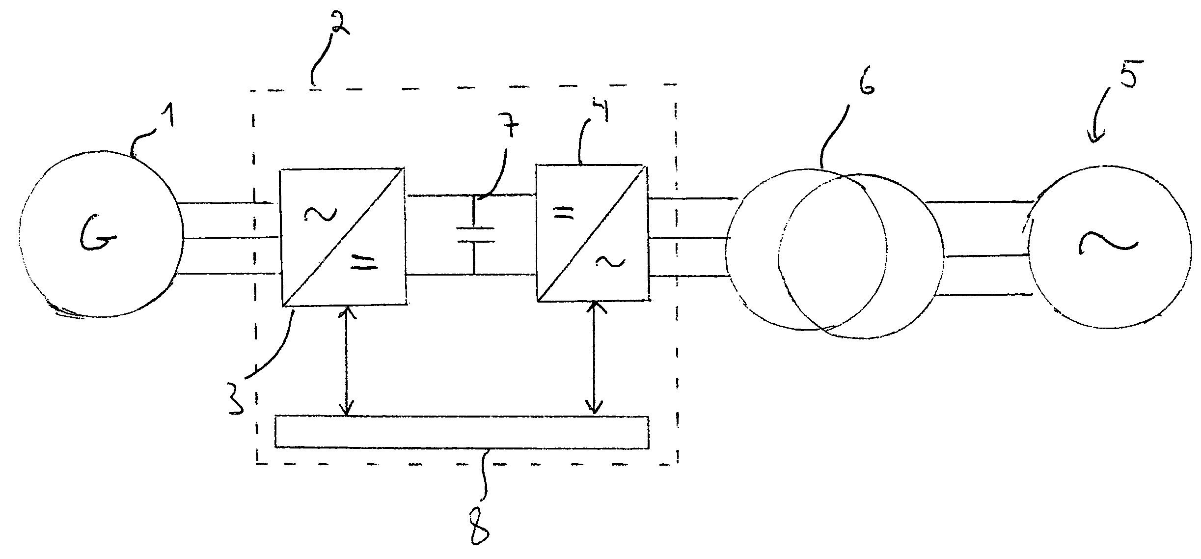
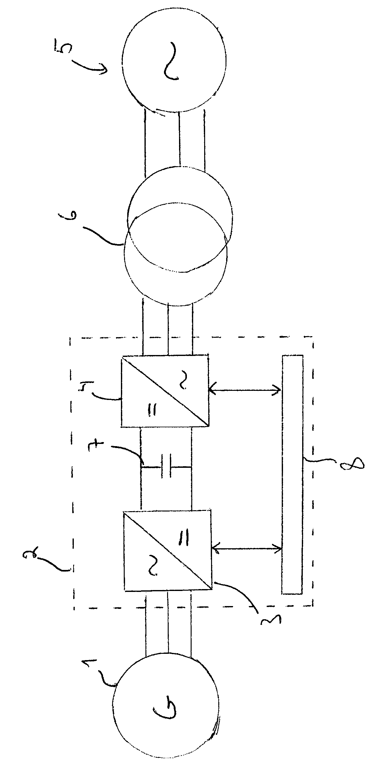
[0011]FIG. 1 schematically illustrates a switching between a generator 1, a frequency converter 2 and a network 5, where the generator 1 produces electricity that is transferred to the network through the frequency converter 2. A transformer is used to transform the voltage level of the output voltage to correspond to the network voltage level.

[0012]FIG. 1 does not illustrate the mechanical power source driving the generator. Such a power source may be a wind turbine and the generator may be a synchronous machine or an induction machine, for instance.

[0013]The frequency converter 2 in FIG. 1 comprises an inverter part 3 and a network converter part 4. The function of the inverter part is to transfer, by means of torque control, the power produced by the generator to a DC voltage intermediate circuit provided with a capacitor 7 for the DC intermediate circuit. The inverter part is implemented by controllable semiconductors in a known manner as a bridge circuit, and thus the torque ma...


PUM


Abstract

A method in a frequency converter provided with a voltage intermediate circuit in connection with interference in a network (5) to be supplied and a frequency converter (2), which comprises a network converter part (4) and an inverter part (3) and a DC intermediate circuit (7) between them. The method comprises steps of controlling the intermediate circuit voltage at the beginning of network interference by limiting the torque on the inverter side, detecting interference in the network voltage, setting a torque reference to a predetermined value in response to the network interference, detecting network voltage recovery, and controlling the torque reference to a normal value in response to the network voltage recovery.

Description

BACKGROUND OF THE INVENTION[0001]The invention relates to a method in a frequency converter provided with a voltage intermediate circuit and to a frequency converter. In particular, the invention relates to the operation of a frequency converter in connection with interference in network voltage.[0002]A frequency converter is a device which is generally used in connection with motors and generators. In motor use, the frequency converter is supplied by the network and it generates voltage for the motor for controlling it in the desired manner. In direct generator use, i.e. in a use where the power generated by the generator is transferred through the frequency converter, the frequency converter may convert the voltage generated by the generator into voltage that can be supplied to the network.[0003]Many existing frequency converters create an electric model of the machine to be controlled. This model provides the frequency converter with as accurate information as possible on the ele...

Claims


Application Information

Patent Timeline
Patent Type & Authority Patents(United States)
IPC IPC(8): H02P9/44H02M5/45H02MH02M5/458H02P27/06
CPCH02M5/458H02P27/06
Inventor YLPPO, JUKKATURUNEN, KARI
Owner ABB (SCHWEIZ) AG
Learn More