
Data burst scheduling

a data burst and scheduling technology, applied in the field of data burst switching, can solve the problems of burst loss, burst loss, burst loss,

Inactive Publication Date: 2007-05-08
RPX CLEARINGHOUSE
View PDF10 Cites 48 Cited by
  • Summary
  • Abstract
  • Description
  • Claims
  • Application Information

AI Technical Summary

Benefits of technology

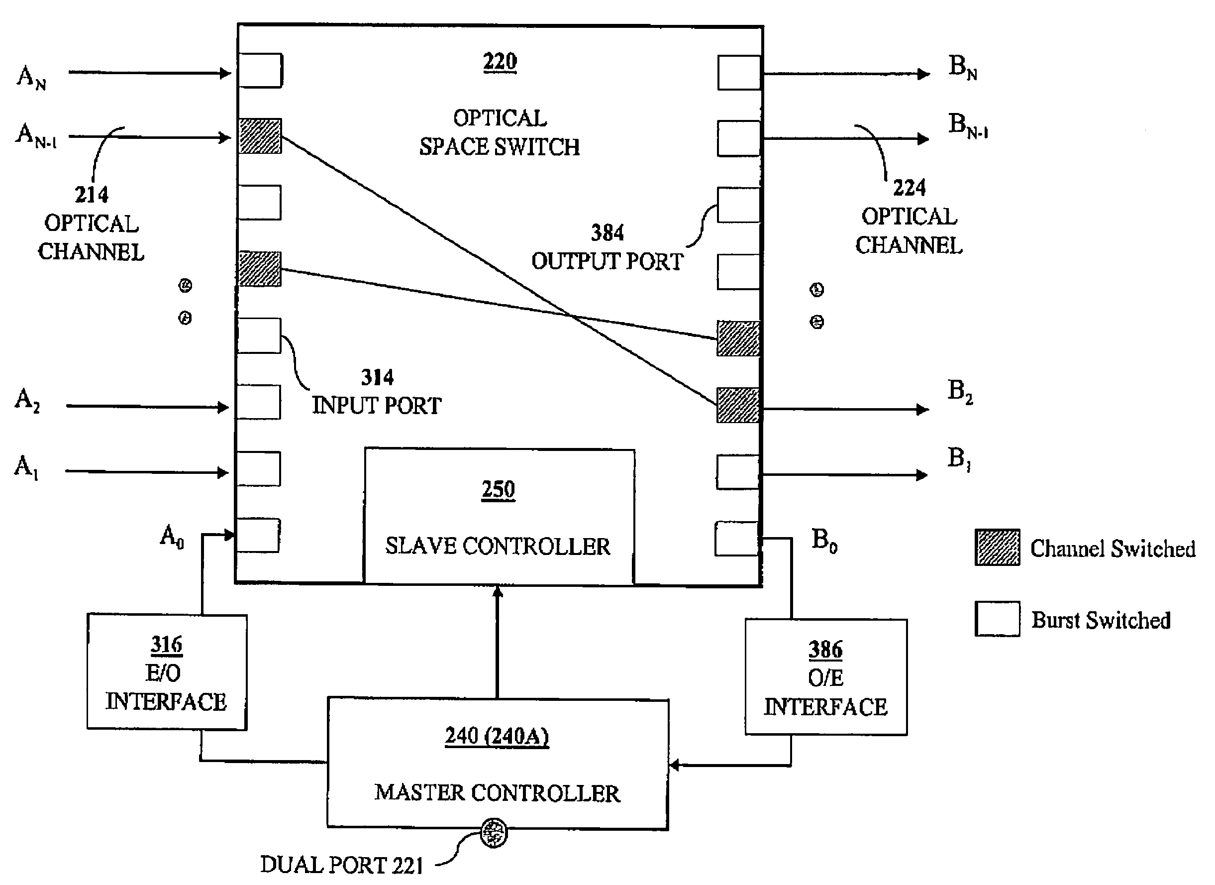
[0012]Methods of scheduling the transfer of data bursts among edge nodes, having buffering facilities, through bufferless core nodes are devised to reduce processing effort and increase overall network efficiency. At each core node, each of several burst-schedulers determines, using parallel comparators, the proximity of available times of selected input ports and selected output ports indicated in a set of candidate burst descriptors and schedules a data burst according to said proximity.
[0013]In a preferred mode of operation of a burst-switched network, rather than sending requests to schedule data bursts after they are received at a respective source node, each source node determines the bitrate requirements for paths to each sink node and sends bitrate-allocation requests to a selected core-node controller which computes burst-transfer permits and sends the permits to corresponding edge nodes. This reduces the scheduling delay while avoiding data loss at the core node.
[0021]In accordance with yet another aspect of the present invention, there is provided a method of confining connections from each upstream link to each downstream link to a small number of space switches in a core node. Bitrate requirements for connections belonging to each upstream link are sorted in a descending order and cyclically assigned to the space switches in a manner that attempts to reduce the number of burst streams for the same total burst-traffic load.

Problems solved by technology

On the other hand, for a given nodal degree, scalability generally increases with the network diameter, but to the detriment of network efficiency.
Prior-art burst switching has attractive features but has two main drawbacks: burst-transfer latency and burst loss.
It is noted that even if a very long time gap is kept between a burst-transfer request and the data burst itself, the lack of buffers at the core node may result in burst loss and a significant idle time.
In the closed-loop scheme, the time delay involved in sending a burst transfer request and receiving an acceptance before sending a burst may be unacceptably high, leading to idle waiting periods and low network utilization in addition to requiring large storage at the edge nodes.
In the open-loop scheme, a burst may arrive at a core node before the optical switch can be configured to switch the burst and the burst may be lost.
Furthermore, the fact that the burst has been lost at the core node remains unknown to the source node for some time and a lost burst would have to be sent again after a predefined interval of time.
This renders closed-loop burst scheduling inappropriate.
The high round-trip delay requires that the source node have a sizeable buffer storage.
On the other hand, open-loop burst scheduling, which overcomes the delay problem, can result in substantial burst loss due to unresolved contention at the core nodes.
However, a burst has to wait at its source node for a period of time slightly exceeding a round-trip delay between the source node and a selected core node.

Method used


Image

  • Data burst scheduling
  • Data burst scheduling
  • Data burst scheduling

Examples


Embodiment Construction

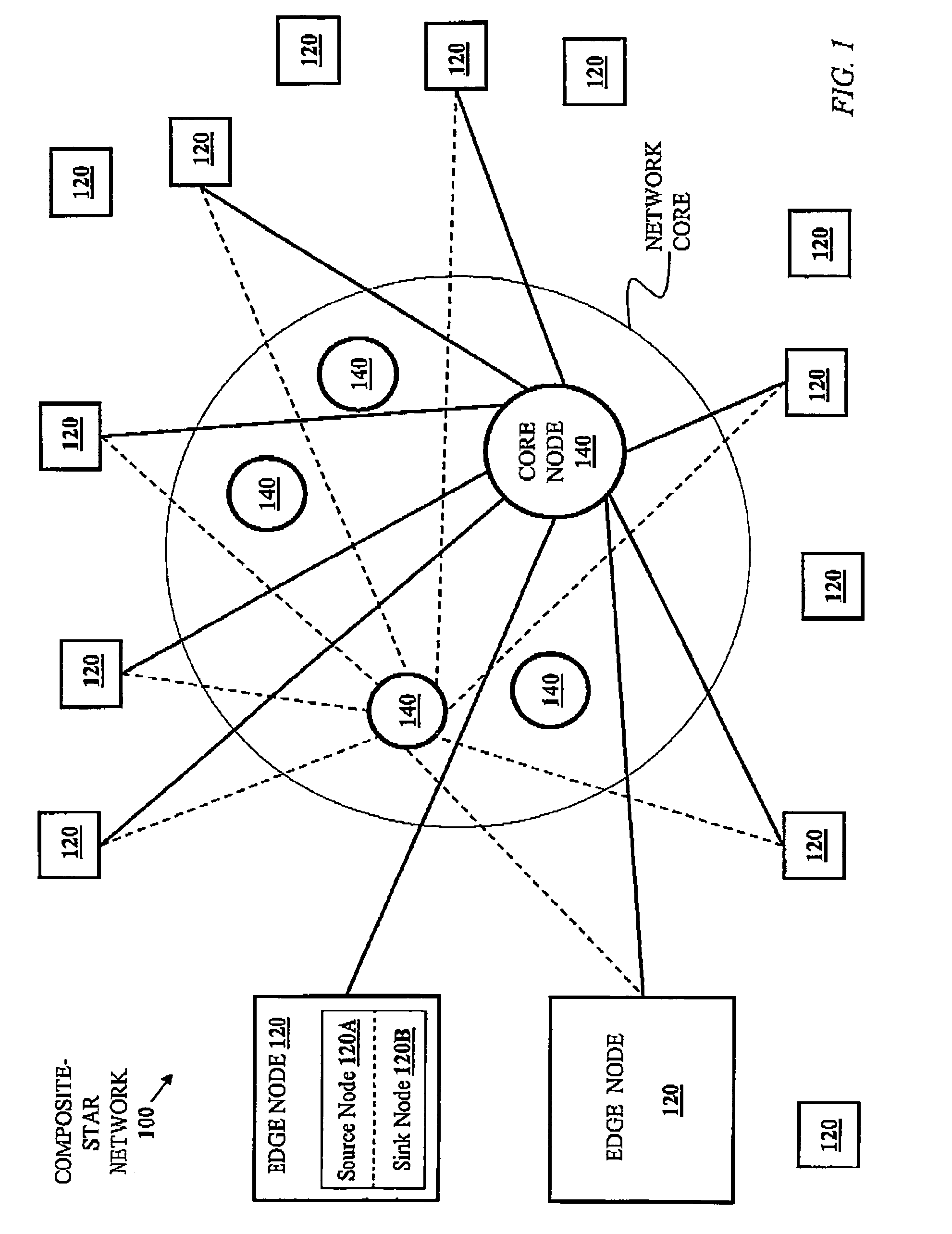
[0057]A star network's main attraction is its high performance and simplicity of control. However, it is suitable only for limited geographic or topological coverage. A composite star network 100, illustrated in FIG. 1, may be viewed as a superposition of several star networks which are merged only at the edge nodes 120 while the core nodes 140 can be widely distributed and independent. An edge node 120 comprises a source node 120A and an associated sink node 120-B. Hereinafter, reference to an edge node 120 also implies reference to the source node 120A and the sink node 120B that constitute the edge node 120. Similarly, reference to a source node 120A or a sink node 120B implies reference to the edge node 120 to which either belongs. The core nodes 140 of a composite-star network are not connected to each other. The composite-star network 100 retains the attractive properties of a star network while providing a wide geographic and topological coverage. The composite-star network 1...


PUM


Abstract

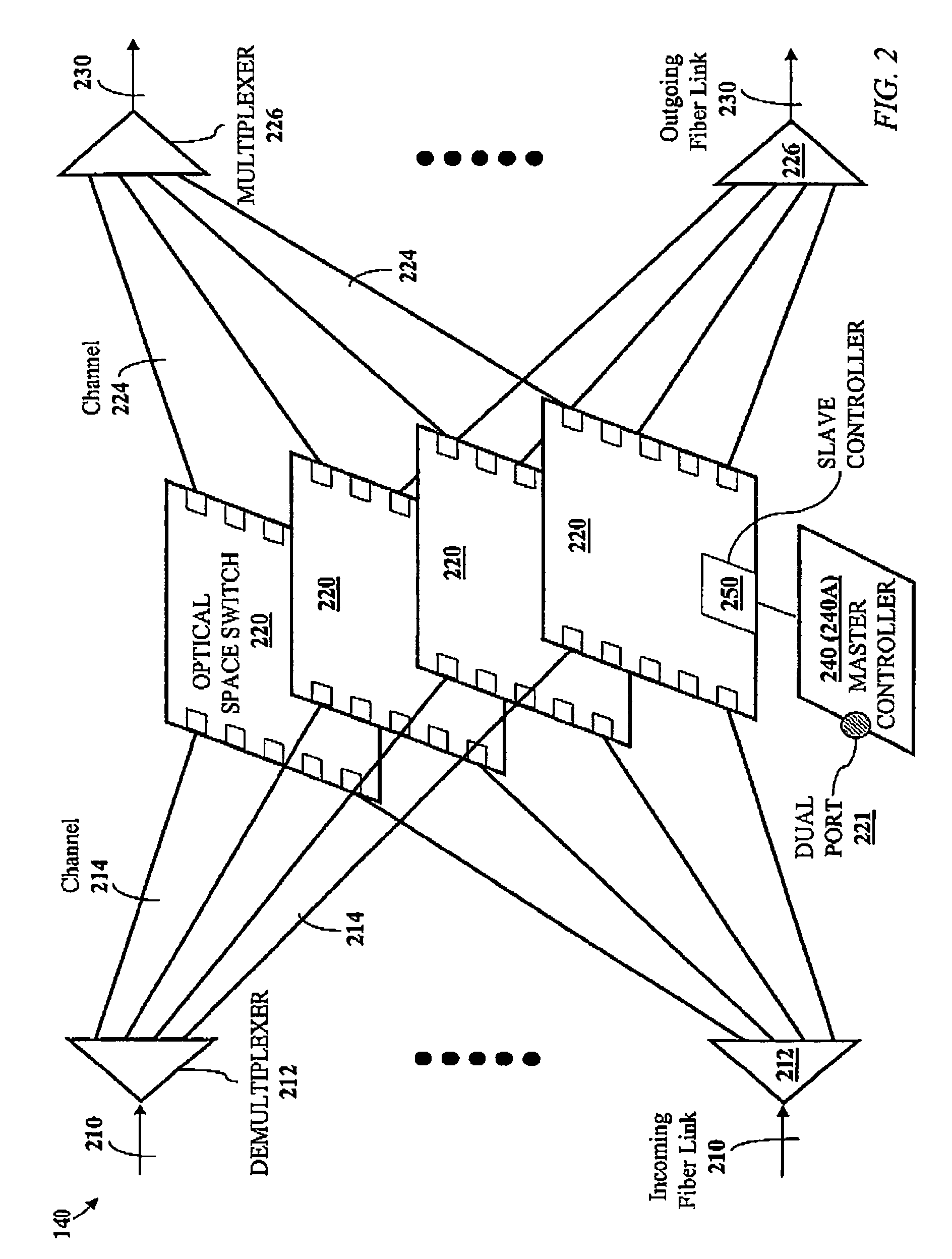
A method and apparatus for scheduling the transfer of data bursts in a network comprising electronic edge nodes interconnected by bufferless core nodes are disclosed. Each edge node comprises a source node and a sink node, and each core node comprises several bufferless space switches operated in parallel. Each source node is connected to at least one core node by an upstream link that includes multiple upstream channels. Each core node is connected to at least one sink node by a downstream link that includes multiple downstream channels. Any of the space switches can have either an electronic fabric or a photonic fabric. Each space switch has a master controller, and one of the master controllers in a core node is designed to function as a core-node controller in addition to its function as a master controller. Each master controller has a burst scheduler operable to compute a schedule for the transfer of data bursts, received from source nodes, to destination sink nodes.

Description

FIELD OF THE INVENTION[0001]The present invention relates to data networks and, in particular, to burst switching in an optical-core network.BACKGROUND OF THE INVENTION[0002]A data network comprises a number of source nodes, each source node receiving traffic from numerous traffic sources, and a number of sink nodes, each sink node delivering data to numerous traffic sinks. The source nodes can be connected to the sink nodes directly or through core nodes. Source nodes and sink nodes are often paired to form edge nodes, where a source node and sink node of an edge node share memory and control.[0003]Each link between two nodes may comprise multiple channels. An optical multi-channel link uses Wavelength Division Multiplexing (WDM). WDM allows a given optical link to be divided into multiple channels, where a distinct stream of data may be transmitted on each channel and a different wavelength of light is used as a carrier wave to form each of the multiple channels within the optical...

Claims


Application Information

Patent Timeline
IPC IPC(8): H04L12/50H04B10/20H04J14/00
CPCH04Q11/0066H04Q2011/0064H04Q2011/0088
Inventor BESHAI, MAGED E.JAMOUSSI, BILEL N.
Owner RPX CLEARINGHOUSE
Learn More