Height control linkage for a vehicle cab suspension

a technology for cab suspensions and cabs, which is applied in the direction of roofs, vehicle arrangements, transportation and packaging, etc., can solve the problems of time-consuming and ergonomic disadvantage in the assembly of the rod arm of the '038 patent, and achieve the effects of convenient length adjustment, durable use, and economical manufactur

Active Publication Date: 2007-05-15
LINK MFG
View PDF7 Cites 15 Cited by
  • Summary
  • Abstract
  • Description
  • Claims
  • Application Information

AI Technical Summary

Benefits of technology

[0010]Still another object of the invention is to provide a height control linkage for a vehicle cab suspension system which is easily length adjusted in the field.
[0011]Still another object of the invention is to provide a height control linkage for a vehicle cab suspension system which is economical of manufacture and durable in use.

Problems solved by technology

It is believed that the assembly of the rod arm of the '038 patent is time-consuming and ergonomically disadvantageous.

Method used


Image

  • Height control linkage for a vehicle cab suspension
  • Height control linkage for a vehicle cab suspension
  • Height control linkage for a vehicle cab suspension

Examples


Embodiment Construction

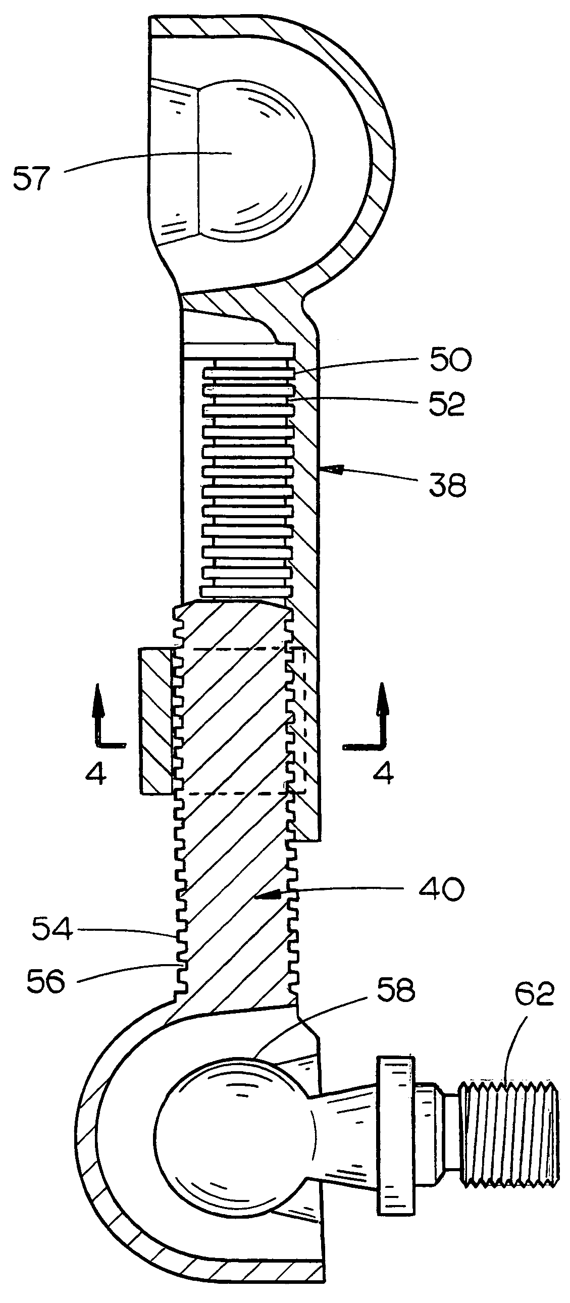
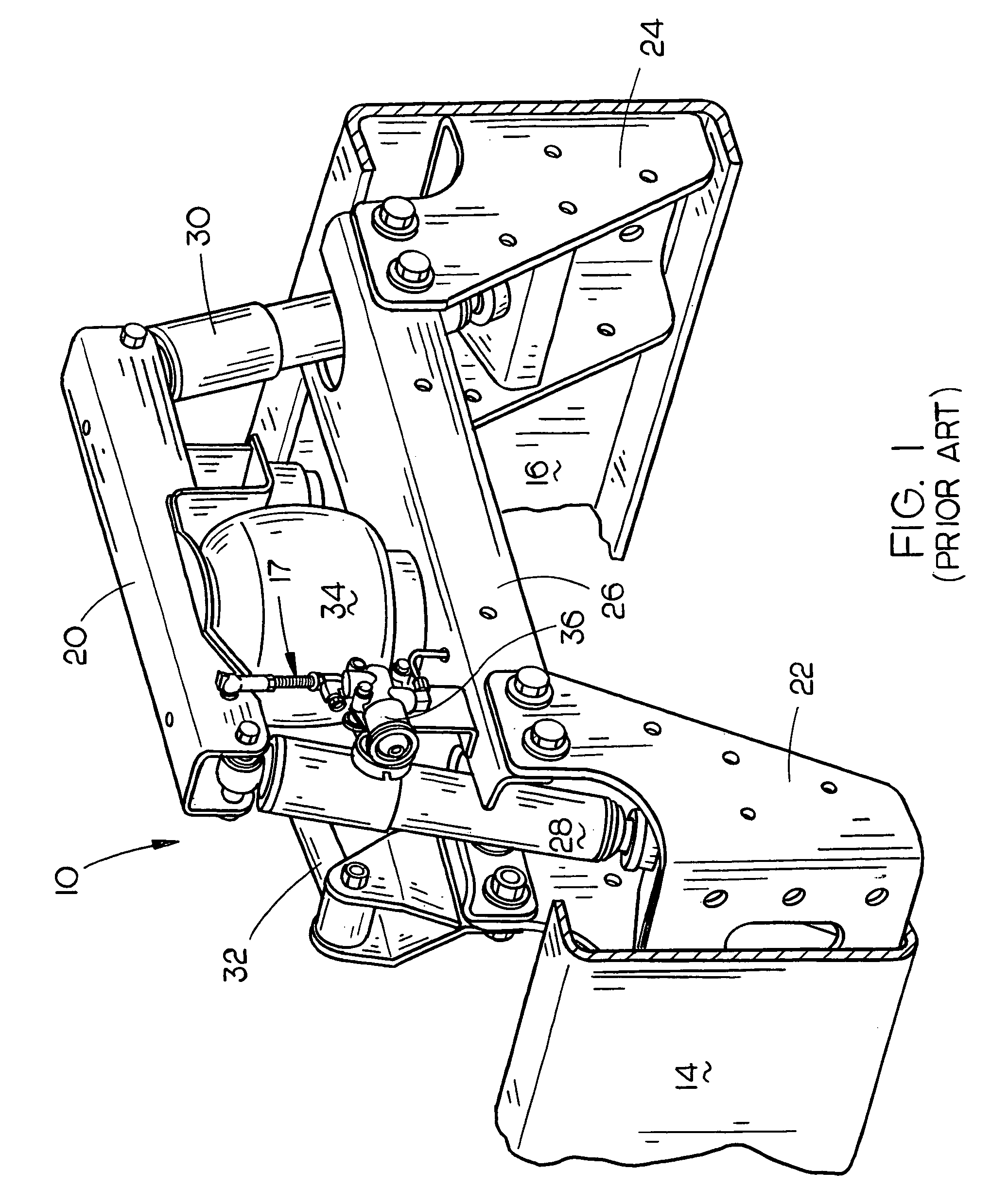
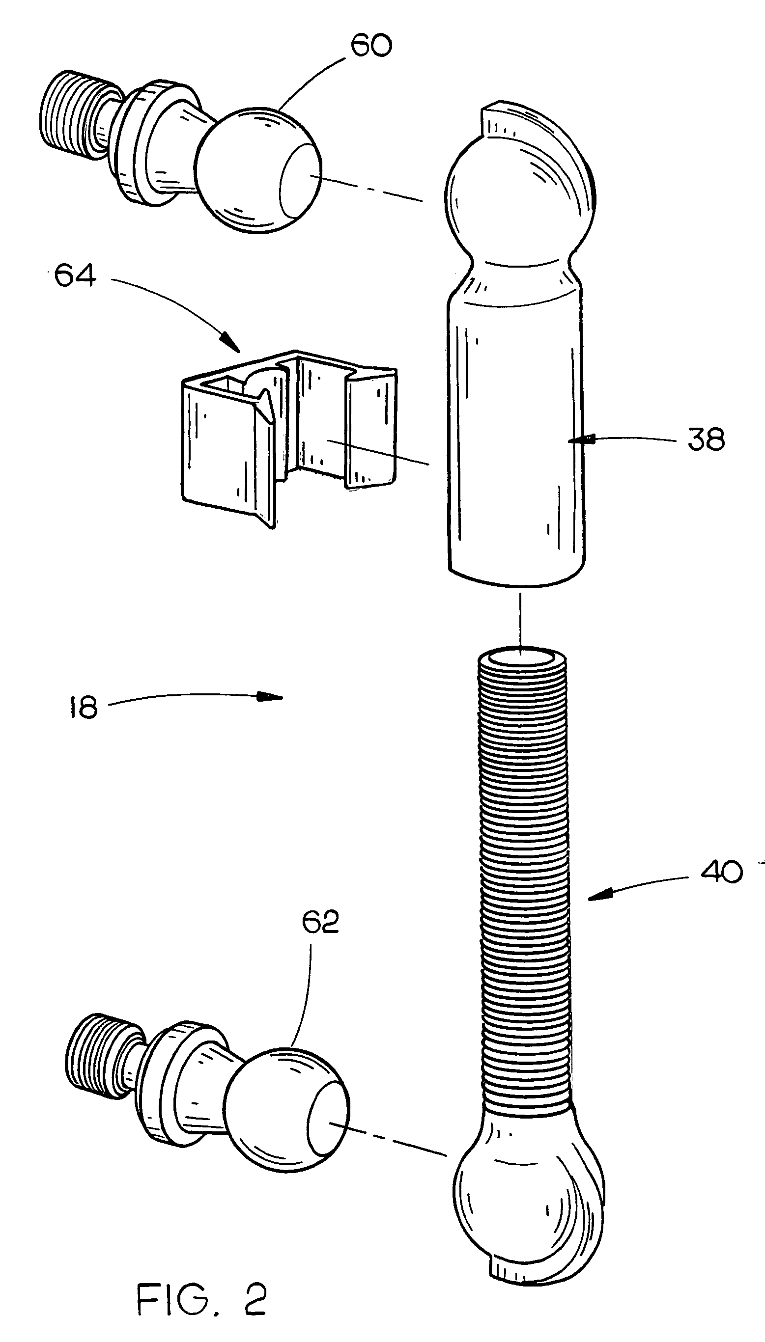
[0018]The numeral 10 refers generally to a prior art cab suspension system which is designed to be used at the rearward end of a vehicle cab between the cab and the chassis or frame of a vehicle to provide relative vertical movement therebetween. Normally, the forward end of the cab is pivotally secured to the chassis at a pair of spaced-apart locations whereby the cab may pivot, about a horizontal axis, with respect to those pivot locations. The vehicle upon which the cab is mounted normally consists of a pair of frame rails 14 and 16. The cab suspension system 10 disclosed in the drawings is identical to or similar to many types of cab suspension systems which include a height control linkage 17. In the prior art suspension systems, the linkage 17 comprises at least a pair of linkage members which are threadably secured together and which may be threadably rotatably moved with respect to one another to change or adjust the length thereof. As stated hereinbefore, the assembly and a...


PUM


Abstract

A height control linkage for a vehicle cab suspension comprising elongated lower and upper linkage members, each of which has upper and lower ends. The lower linkage member has external, vertically spaced-apart, alternating ridges and grooves formed thereon for at least a portion thereof above its lower end. The lower end of the upper linkage member has a generally C-shaped cross-sectional portion defining a gap. The generally C-shaped portion of the upper linkage member has internal, vertically spaced-apart, alternating ridges and grooves which are complementary to the external ridges and grooves of the lower linkage member. The upper end of the lower linkage member is adapted to be vertically adjustably snap-fitted through the gap of the upper linkage member to connect the lower linkage member to the upper linkage member. A snap-clip is provided to maintain the linkage members in their connected relationship. Rotation of one of the linkage members with respect to the other linkage member does not result in a change in the length of the linkage. The linkage members and the snap-clip are preferably comprised of a molded plastic material. The linkage of this invention may be used to link components other than vehicle cab suspensions.

Description

BACKGROUND OF THE INVENTION[0001]1. Field of the Invention[0002]This invention relates to a height control linkage for a vehicle cab suspension and more particularly to a height control linkage for a vehicle cab suspension comprised of elongated lower and upper linkage members with the linkage members being able to be snapped together. Although the height control linkage is primarily designed to be used with cab suspension systems, it may also be used with vehicle chassis suspension systems.[0003]2. Description of the Related Art[0004]Many vehicle cab suspensions have been previously provided for supporting a vehicle cab on the chassis of the vehicle whereby a cushioning or shock absorber effect is achieved to provide a more comfortable ride for the occupant or occupants of the cab. Further, many vehicle cab suspensions have been previously provided for adjusting the height of the rear of the cab depending upon the weight of the occupants, etc., within the cab. For example, see U.S....

Claims


Application Information

Patent Timeline
Patent Type & Authority Patents(United States)
IPC IPC(8): B62D24/04
CPCB62D33/0608
Inventor ABELE, DENNIS LYNNHULSTEIN, GREGORY W.
Owner LINK MFG
Why Eureka
Try Eureka