Method for testing the fit or imbalance of a tool

a technology of tool fit and imbalance, applied in the direction of maintenance and safety accessories, measurement/indication equipment, automatic control devices, etc., can solve the problems of a relatively long check-in procedure and other problems, and achieve the effect of simple and rapid method

Inactive Publication Date: 2007-05-15
CROSS HULLER
View PDF15 Cites 8 Cited by
  • Summary
  • Abstract
  • Description
  • Claims
  • Application Information

AI Technical Summary

Benefits of technology

[0007]The object of the invention is to provide a simple and rapid method for testing fit or imbalance.
[0015]The fundamental recognition of the invention is that an intermittent signal path indicates an irregularity, i.e. a non-aligning fit or a tool imbalance. Moreover, it is possible to derive further information about the nature and extent of the irregularity using the first relative position which may then be detected and in which the intermittent signal path appears for the first time. The method according to the invention requires virtually no separate components. It uses in particular the means which are already provided for the three-dimensional positioning of the tool spindle and the light barrier known for avoiding thermally induced changes in position of the tool. Thus, the additional expense in terms of apparatus for the method according to the invention for fit or imbalance testing is fundamentally negligible. Moreover, all the working steps of the method according to the invention may be carried out quickly. In particular, it is possible to measure a light beam within a very short time.
[0016]An embodiment wherein a second relative position is detected between the tool spindle and the light beam, in which second relative position the received signal has an intermittent signal path for the last time, and is then evaluated allows a more accurate determination of the irregularity. Using the two detected relative positions, it is possible to determine the minimum and also the maximum extent of a wobbling movement of the tool caused by the irregularity. When a difference value is produced from the first and second relative positions, it is easily possible to provide information about the double extent of the wobbling movement. A simpler improved evaluation is possible by taking into account the double extent determined in this manner.
[0017]When the difference value is compared with previously determined and stored error reference values makes it easily possible to specify in more detail the prevailing irregularity using a table with known types of irregularities.

Problems solved by technology

The checking procedure also takes a relatively long time, since the drop in pressure to be analysed generally only takes place slowly.

Method used


Image

  • Method for testing the fit or imbalance of a tool
  • Method for testing the fit or imbalance of a tool
  • Method for testing the fit or imbalance of a tool

Examples


Embodiment Construction

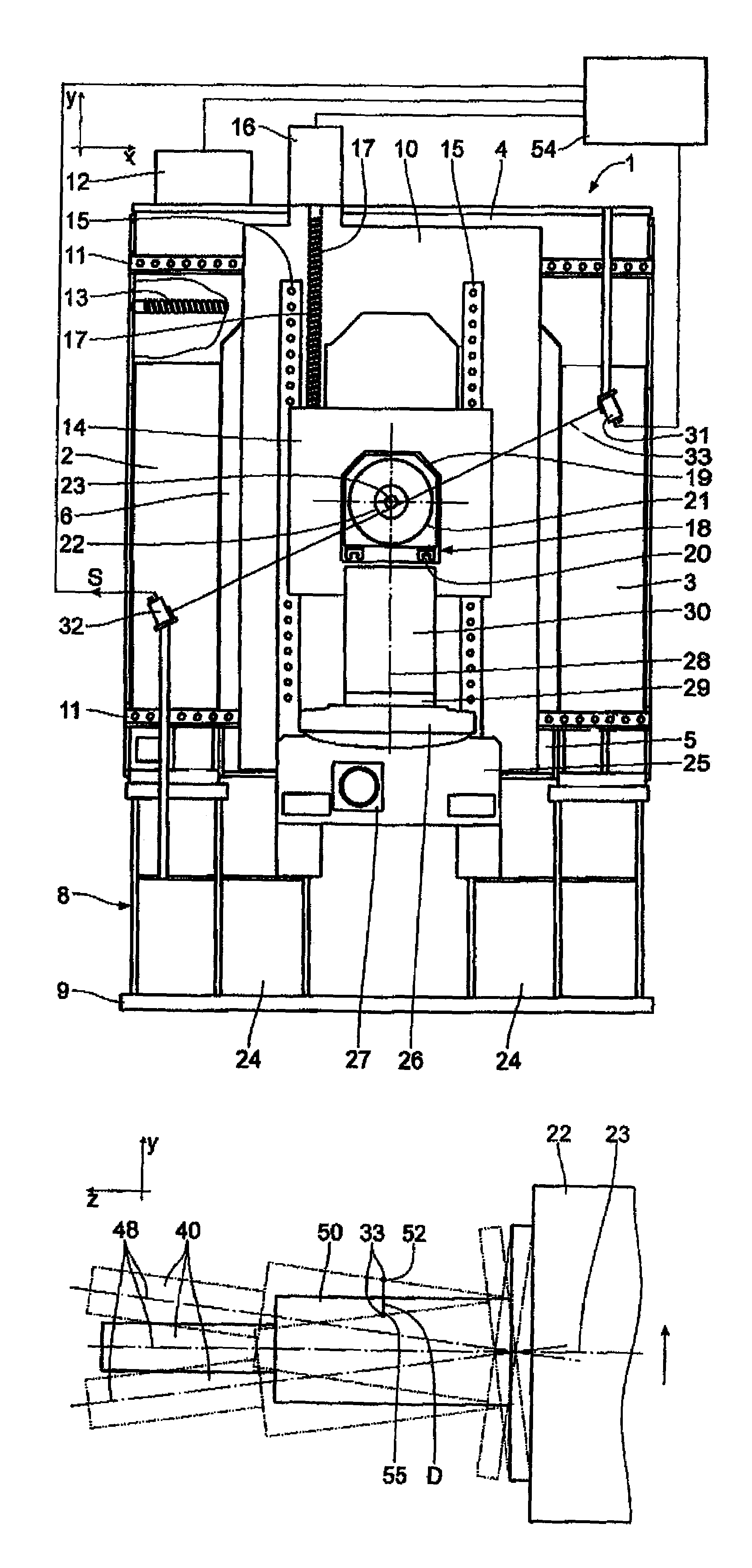
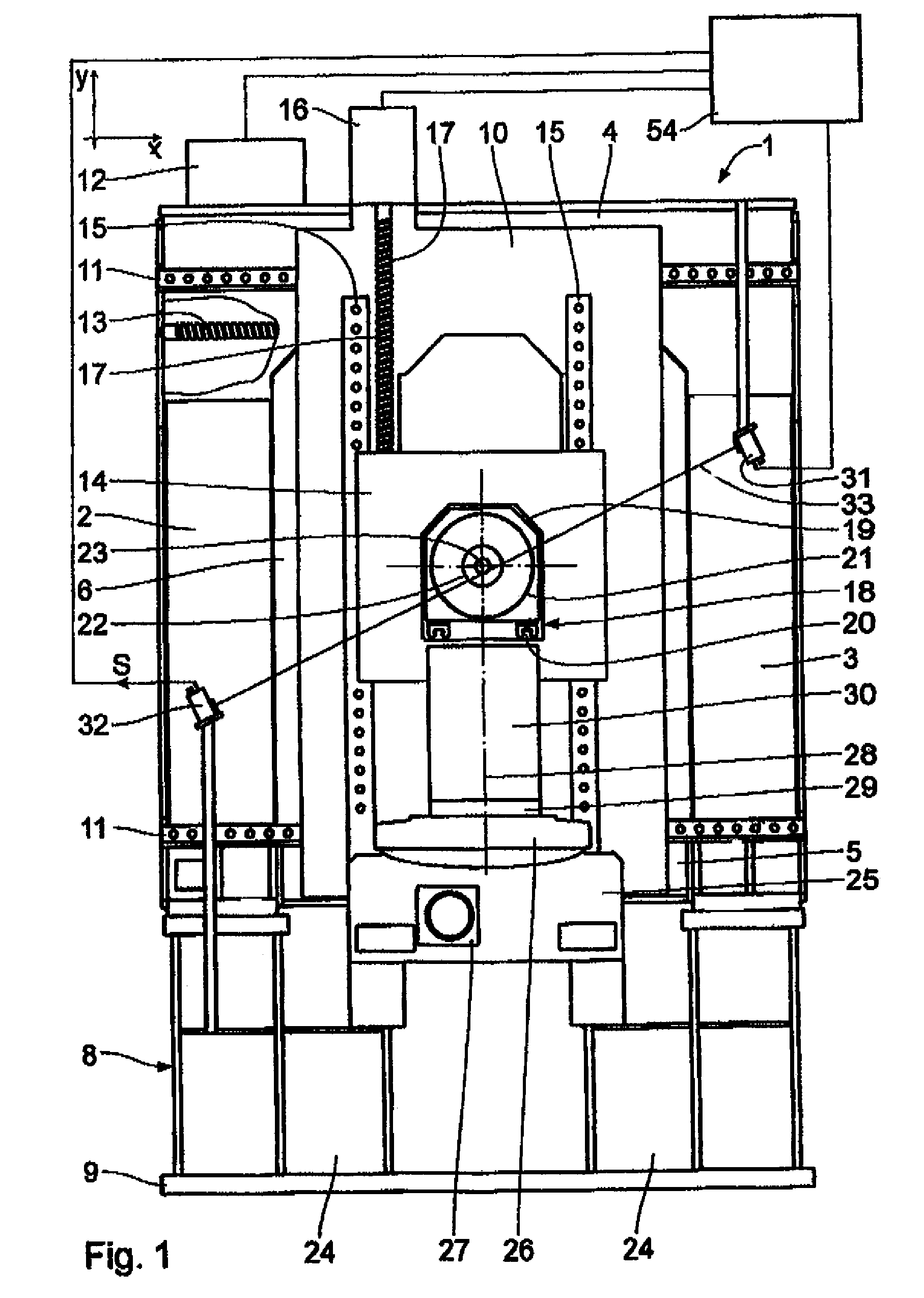
[0026]The machine tool shown in FIG. 1 has a stand 1 which, seen in the horizontal z-direction, is rectangular, that is, approximately square, and is formed by a frame and by vertical side supports 2, 3 extending in the y-direction and by a respective horizontal upper cross spar 4 and lower spar 5 extending in the x-direction and joining these supports 2, 3. The side supports 2, 3 and the cross spars 4, 5 are formed by hollow profiles and enclose an interior 6 which is open at both ends seen in the z-direction, that is, in particular towards a work area 7. The stand 1 is supported on a foundation or a foundation plate 9 by an underframe 8.

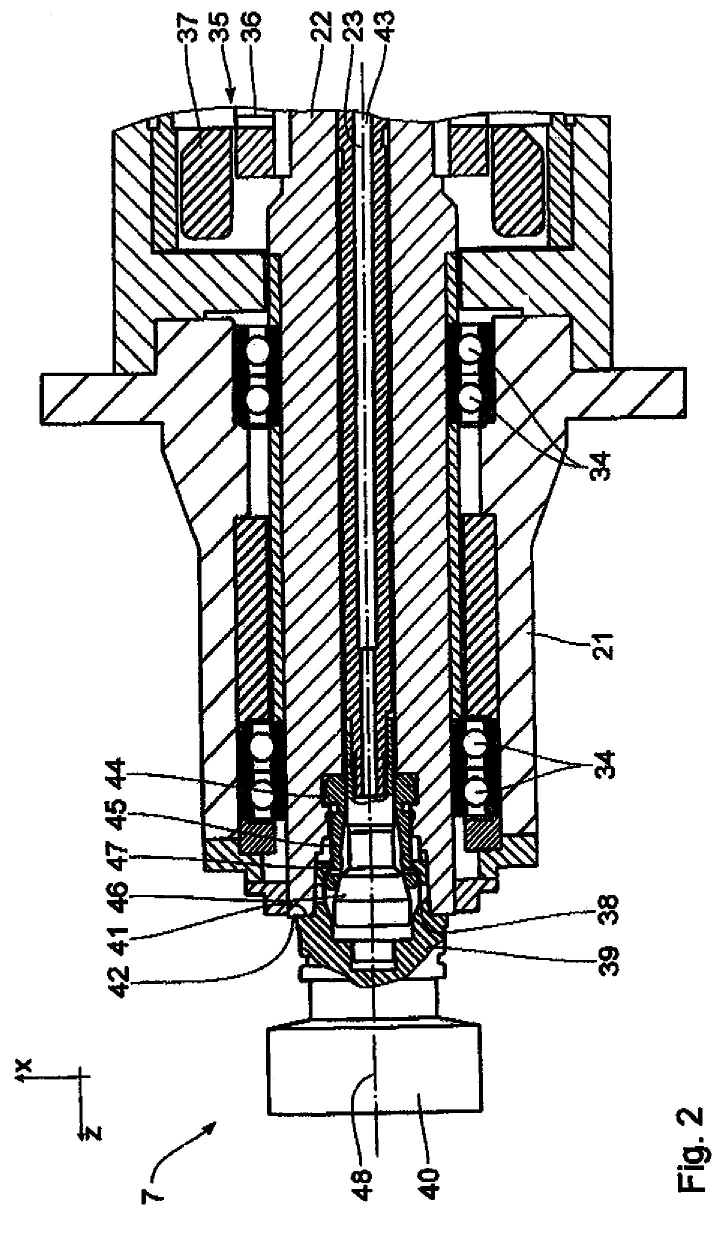
[0027]An x-slide 10 which is also configured in the manner of a frame is positioned to be movable in the x-direction on the end face of the stand 1 facing the work area 7. A respective x-guide rail 11, on which the x-slide 10 is guided, is positioned on the cross spars 4, 5. The x-slide 10 is driven by an x-motor 12 via an x-axis spindle 13 extendi...


PUM

PropertyMeasurementUnit
distanceaaaaaaaaaa
pressureaaaaaaaaaa
timeaaaaaaaaaa

Abstract

In the method, a tool is tested for an aligning fit or an imbalance in a tool spindle. The tool spindle is set into rotation. A light beam is used to check whether the tool wobbles. The tool spindle and the light beam are moved relative to one another until the light beam impinges on the area covered by the wobbling movement and a received signal generated from the light beam has an intermittent signal path for the first time. The then prevailing relative position between the tool spindle and the light beam is evaluated in respect of a non-aligning fit of the tool or in respect of a tool imbalance.

Description

BACKGROUND OF THE INVENTION[0001]1. Field of the Invention[0002]The invention relates to a method for testing the fit or imbalance of a tool which is accommodated in a replaceable manner in a tool spindle mounted so that it may be driven in rotation about a central longitudinal axis.[0003]A tool spindle of this type is used in a machine tool. In order to achieve high machining accuracy, the inserted tool should run as true as possible. Deviations from concentricity may result due to a non-aligning fit, caused by contaminants, of the tool in the tool spindle or due to some types of tool imbalances. Such irregularities are to be detected and rectified.[0004]2. Background Art[0005]It is known from U.S. Pat. No. 6,059,702 to clean the abutment surfaces with compressed air or with the cooling means of the machine tool when the tool is inserted. Moreover, it is possible to check the correct, i.e. aligning fit of the tool, following insertion, by introducing compressed air and by detecting...

Claims


Application Information

Patent Timeline
Patent Type & Authority Patents(United States)
IPC IPC(8): B23C9/00B23Q15/00
CPCB23Q17/003B23Q17/24G01B11/272Y10S33/21Y10T409/3084Y10T408/21Y10T409/308064Y10T409/303752Y10T409/308176Y10T408/16Y10T409/30728Y10T409/306888
Inventor BAYHA, THOMASBERGER, ANDREAS
Owner CROSS HULLER
Why Eureka
Try Eureka