Compression connector for braided coaxial cable

a compression connector and coaxial cable technology, applied in the direction of coupling devices, two-part coupling devices, electrical equipment, etc., can solve the problems of increasing the cost of hard-line coaxial cables, and reducing the service life of coaxial cables. , to achieve the effect of relieving the compressive stress

Active Publication Date: 2007-05-15
JOHN MEZZALINGUA ASSOC INC
View PDF13 Cites 34 Cited by
  • Summary
  • Abstract
  • Description
  • Claims
  • Application Information

AI Technical Summary

Benefits of technology

[0014]The outer surface of the compression member can include an annular groove at an intermediate portion between the external rib at the first end and the flange at the second end of the compression member. The outer surface may also include a shoulder between the annular groove and the flange that is sized to establish a press fit with the internal diameter of the second end of the connector body sufficient to retain the compression member in a second position fully axially advanced into the connector body. The annular groove may have side walls that can be inclined, perpendicular or radiussed. The annular groove provides for slight bending or flexure of the compression member to relieve the compressive stresses caused upon the axial advancement of the compression member and enables the connector to accommodate variations in the thicknesses of the foil layers, braided outer conductor and protective outer jacket of coaxial cables provided by assorted manufacturers.

Problems solved by technology

However, standard hard-line coaxial cable is quite costly and somewhat difficult to install as compared to large gauge, braided coaxial cable, such as RG11 type cable.
Although such braided coaxial cable does not provide the level of physical protection afforded by standard hard-line coaxial cable, it is comparatively more structurally flexible.
Making this interconnection can be difficult, however, because the ports of most trunk line equipment have a “KS” type connection / interface, which is designed to be compatible with standard hard-line cable and equipment, whereas flexible coaxial cable having a braided outer conductor generally uses an “F” type connection / interface which is incompatible with the KS type ports.
One solution to this problem is to utilize an adapter to connect the incompatible “KS” and “F” connections; however, doing so adds non-nominal assembly costs, requires the workmanship of a skilled technician, and, even if such adapters are installed correctly, can compromise overall communications network performance.
But use of such connectors with braided coaxial cable is not ideal for various reasons, including incompatibility, difficulty of installation and negative performance effects.

Method used


Image

  • Compression connector for braided coaxial cable
  • Compression connector for braided coaxial cable
  • Compression connector for braided coaxial cable

Examples


Embodiment Construction

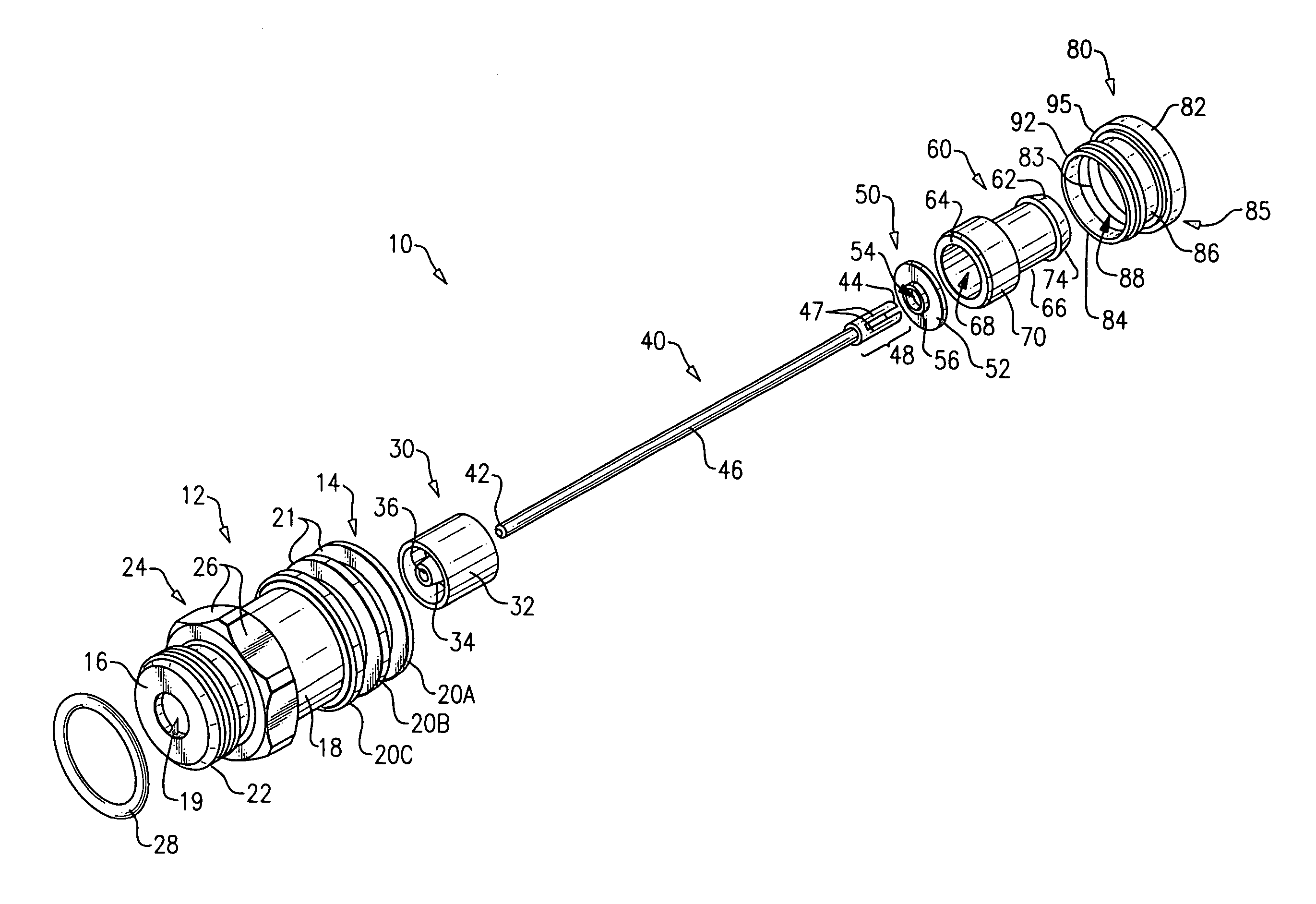
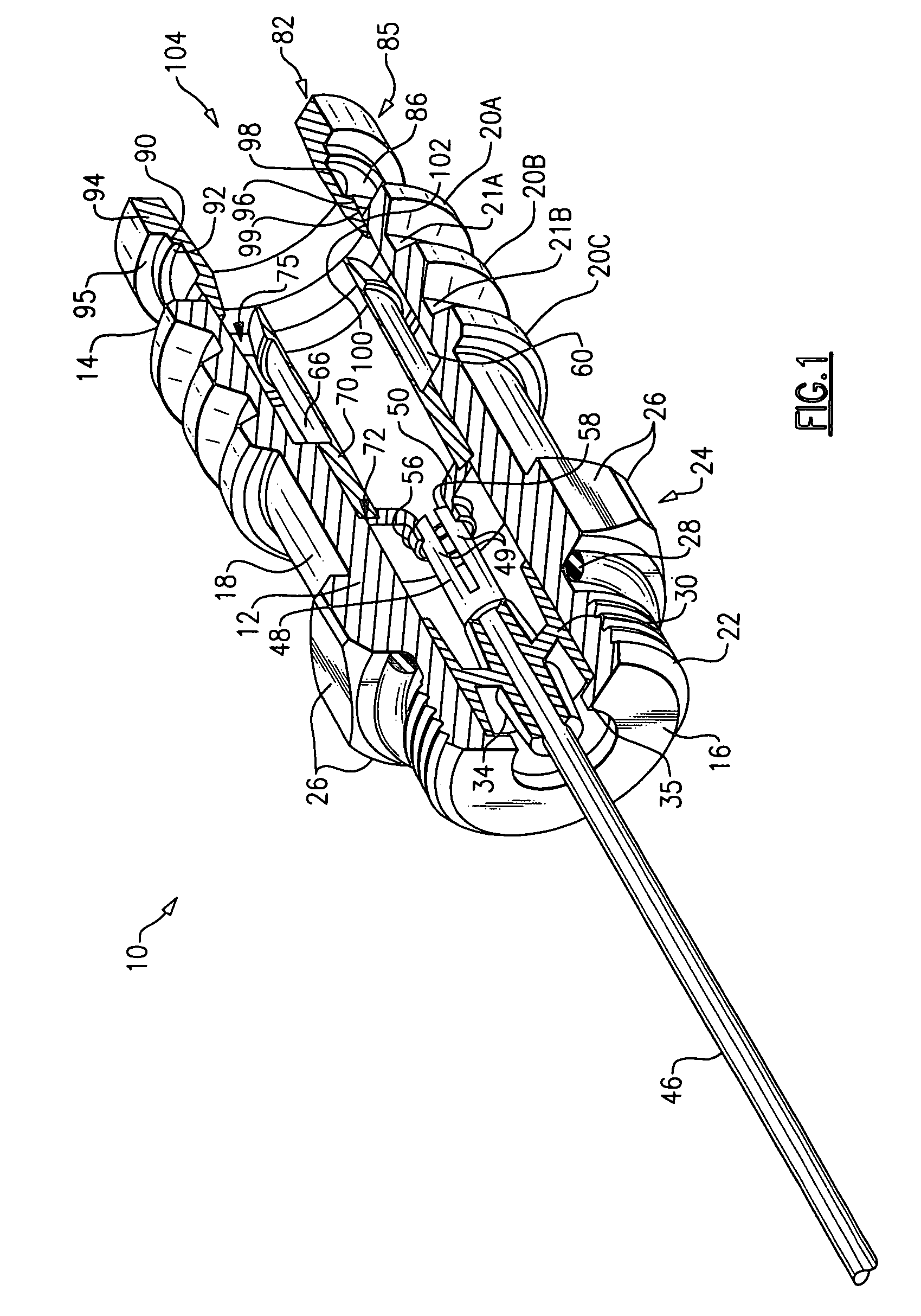
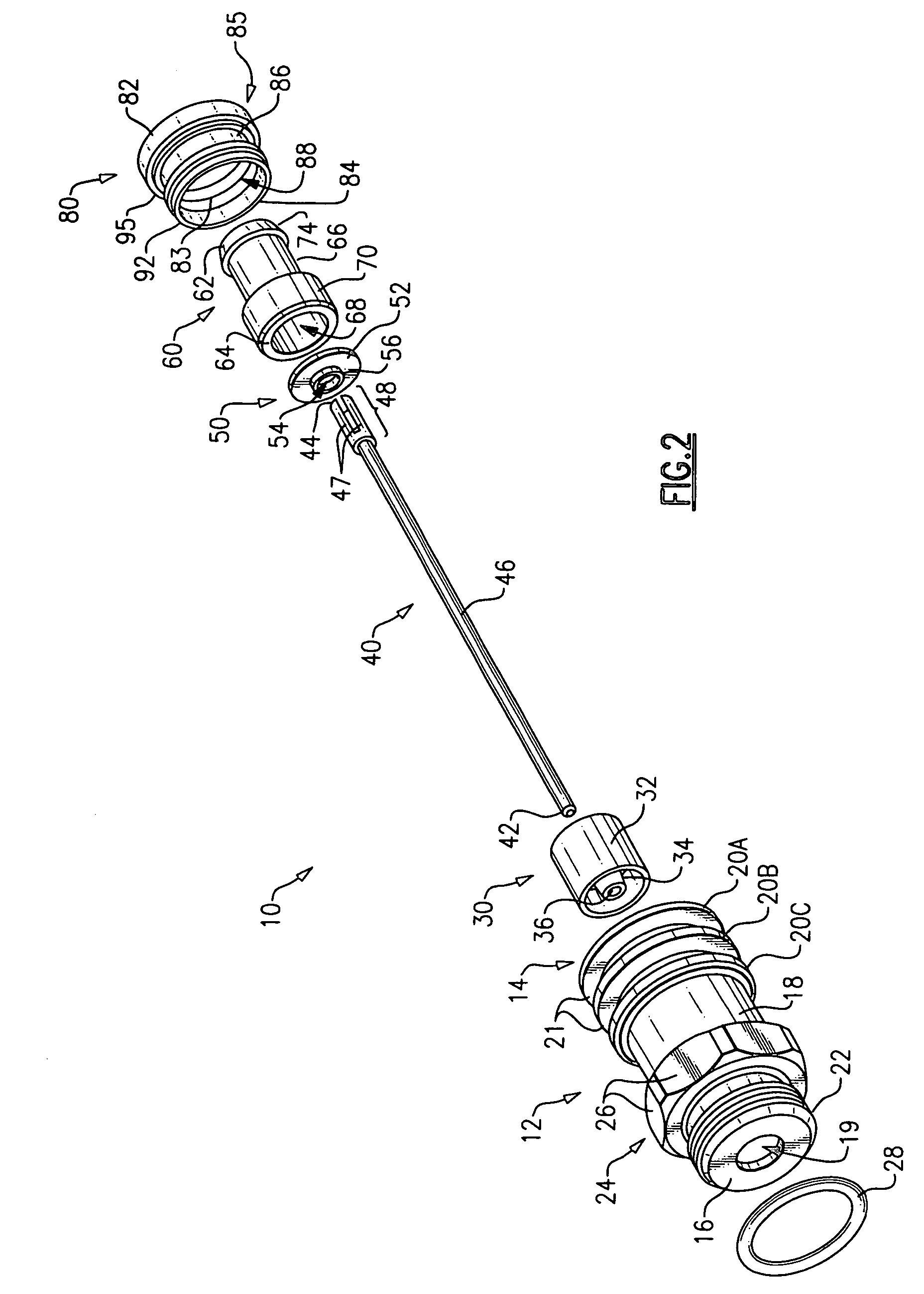
[0027]Referring initially to FIGS. 1 and 2, a device 10 (e.g., a connector) is shown for interconnecting coaxial cable, such as coaxial cable within a communications network, to a trunk line equipment port. The device 10 of the present invention is highly advantageous because due to its structure and design, it is well suited for connecting coaxial cable (e.g., braided coaxial cable, especially large gauge braided coaxial cable as used within CATV networks) to the port of trunk line equipment (e.g., a tap, an amplifier, a filter, a trap, or the like) having a “KS” interface.

[0028]The connector 10 includes a connector body 12, which, according to an exemplary embodiment of the present invention and as shown in FIG. 2, has a generally cylindrical shape. The body 12 has a first end 16 and a second end 14 and a generally cylindrical intermediate portion 18. A plurality of protruding ridges 20A, 20B, 20C are provided between the second end 14 of the body 12 and the intermediary portion 1...


PUM


Abstract

A coaxial cable compression connector for interconnecting braided coaxial cable to a trunk line equipment port is provided, wherein the connector is connected to a trunk line equipment port, a segment of cable is inserted within the connector, and the cable is caused to be radially compressed within the connector so as to provide an inexpensive, reliable and permanent connection between the braided coaxial cable and the connector without the usage of an adapter or a swivel joint.

Description

CROSS-REFERENCE TO RELATED APPLICATIONS [0001]This application is a continuation in part of U.S. application Ser. No. 11 / 092,197 filed Mar. 29, 2005 now U.S. Pat. No. 7,048,579, which is a continuation of part of U.S. application Ser. No. 10 / 892,645 filed Jul. 16, 2004 now U.S. Pat. No. 7,029,326, which are all incorporated by reference.FIELD OF THE INVENTION [0002]The present invention relates generally to coaxial cable connectors, and more particularly to coaxial cable connectors for providing a reliable connection between braided coaxial cable and trunk line equipment ports without adding unnecessary cost and complexity or negatively affecting network performance.BACKGROUND OF THE INVENTION [0003]Coaxial cable is a typical transmission medium used in modern communications networks, such as CATV networks. The bulk of such networks are generally formed of standard “hard-line” coaxial cable, which includes a rigid or semi-rigid outer conductor and is typically covered with a weather...

Claims


Application Information

Patent Timeline
Patent Type & Authority Patents(United States)
IPC IPC(8): H01R9/05
CPCH01R9/0518H01R9/0524H01R24/40H01R4/5016H01R13/622H01R13/623H01R2103/00
Inventor MONTENA, NOAH
Owner JOHN MEZZALINGUA ASSOC INC
Why Eureka
Try Eureka