Pressure swing reforming for fuel cell systems

a fuel cell and pressure swing technology, applied in the direction of combustible gas production, sustainable manufacturing/processing, separation processes, etc., can solve the problems of limiting the utility of steam reform furnaces in point-of-use fuel applications, occupying a large space, and substantially greater than the volume of tubes

Active Publication Date: 2007-05-15
EXXON RES & ENG CO
View PDF28 Cites 101 Cited by
  • Summary
  • Abstract
  • Description
  • Claims
  • Application Information

AI Technical Summary

Benefits of technology

[0020]The pressure swing reforming process efficiently produces a hydrogen containing synthesis gas that may be used to fuel a fuel cell.

Problems solved by technology

Unfortunately, steam reforming furnaces occupy a very large volume of space, substantially greater than the tube volume.
This feature, and the relatively low efficiency, combine to severely limit its utility in point-of-use fuel applications such as fuel cells and would likely be unfeasible for on-board vehicle applications.
However, gas-phase reaction kinetics tend to over-oxidize some of the feed, resulting in excessive heat generation and substantial yield of H2O, CO2, and unreacted hydrocarbons as soot.
However, autothermal reforming requires a source of oxygen.
In the fuel cell vehicle applications, this oxygen is typically provided as compressed air, which results in a nitrogen-diluted synthesis gas that adversely effects the operating efficiency of the fuel supply / fuel cell and adds the cost and complexity of an additional compressor.
However, these patents describe a process that operates at very low productivity, with space velocities of around 100 hr−1 (as C1-equivalent).
One consequence of Sederquist's low space velocity is that resulting high heat losses impede the ability of this technology to achieve the theoretical high efficiency.

Method used


Image

  • Pressure swing reforming for fuel cell systems
  • Pressure swing reforming for fuel cell systems
  • Pressure swing reforming for fuel cell systems

Examples


example 1

[0081]To illustrate one embodiment of the present invention, an amount of iso-octane was processed using the pressure swing reforming process illustrated in FIG. 4. The hydrogen separation means in this example is a supported palladium membrane, operating at a temperature of about 350° C. Key system parameters are identified in Table 1 below:

[0082]

TABLE 1Stream Identity411,401 + 403407409429430427ReformShiftH2RecycleDepletedFlueFeedOutletProductPurgeAirGasT, ° C.200360350350200420P, Atm ga9909 to 0.50.50gmol. / minIC81.70CH40.408.408H2O20.4063.010.001.3312.1520.04H20.0033.5932.2282.330.000.00CO0.007.320.007.320.000.00CO20.005.8750.005.870.0010.30N20.000.070.000.0079.9679.96O20.000.000.000.005.65ΔHc, kW14317812649

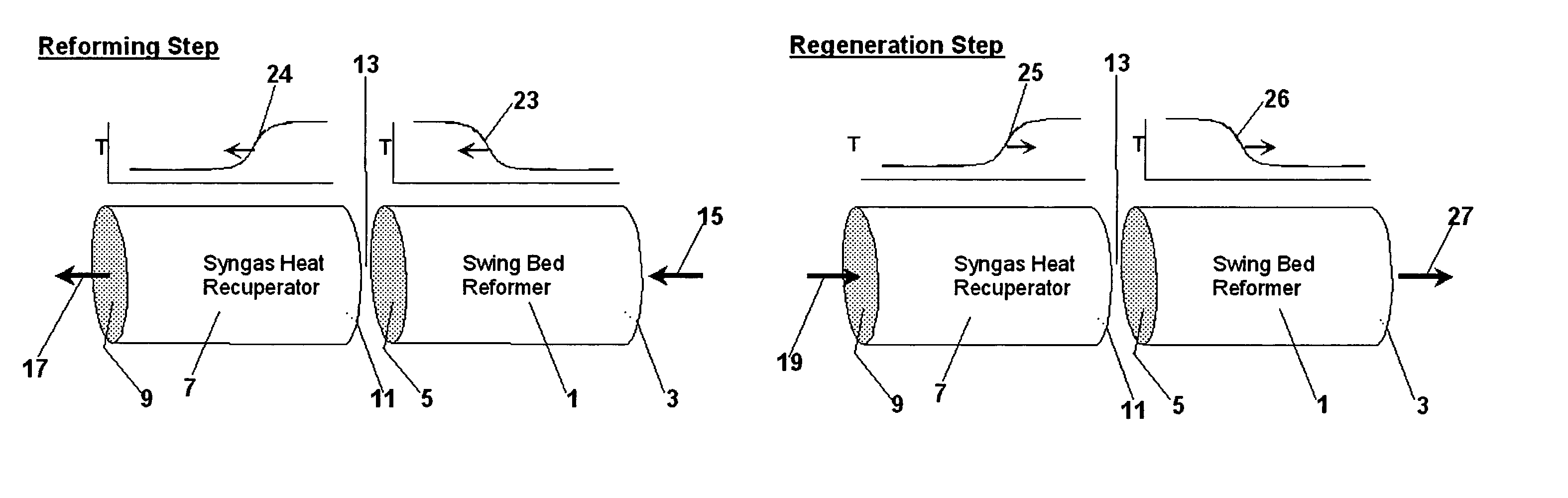
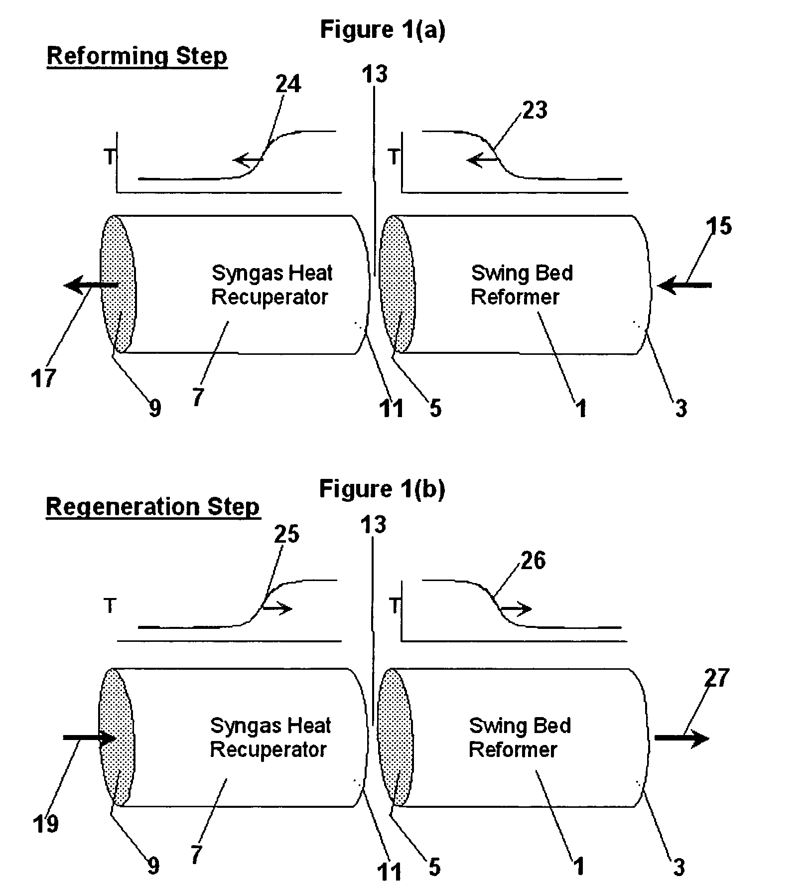
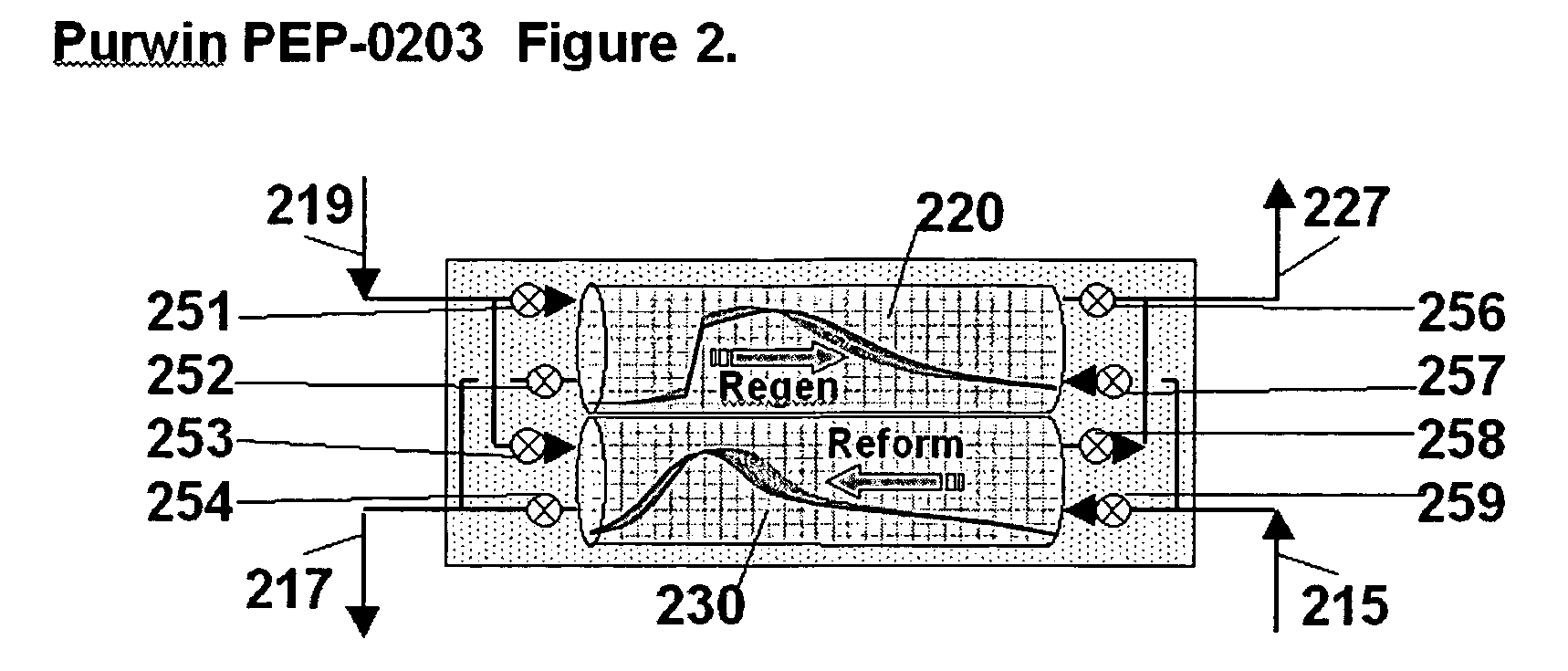
[0083]This example utilizes two PSR reactors, operated as described with respect to FIG. 2 to provide a substantially continuous stream of product. The cycle time is about 15 seconds, with regeneration and reforming each operating about half the cycle. During the reforming ste...

example 2

[0084]To illustrate another embodiment of the present invention, an amount of methane was processed using the pressure swing reforming process illustrated in FIG. 5, but without the steam boiler (502). The hydrogen separation means in this example is a polymer membrane, operating at a temperature of about 100° C. Key system parameters are identified in Table 2 below:

[0085]

TABLE 2Stream Identity501 + 503507509511530527ReformShiftH2RecycleDepletedFlueFeedOutletProductPurgeAirGasT, ° C.400500100100400530P, Atm ga.9919 to 0.50.50gmols / minCH412.370.3700.37H2O20.253.3903.3918.321.89H2039.9237.072.85CO08.2108.21CO203.7703.7712.35N200.0700.0793.493.4O200006.26ΔHc, kW16019914554

[0086]This example makes use of two PSR reactors, operated as described with respect to FIG. 2 to provide a substantially continuous stream of product. The cycle time is 6 seconds, with regeneration and reforming each operating half the cycle. During the reforming step, the fuel flow is terminated about 0.1 sec before...

example 3

[0087]To illustrate another embodiment of the present invention, an amount of methane was processed using the pressure swing reforming process illustrated in FIG. 3. In this example, the fuel cell is a proton conducting solid oxide fuel cell (“SOFC”) operating at about 500° C. SOFC anode and cathode effluents (streams 318&312) are used as PSR regeneration feed (streams 329&330). Waste heat from the SOFC and the regeneration effluent (327) are used to make steam and provide preheat (not shown) of PSR and SOFC feeds, as needed. Water for steam is condensed from a cooled regeneration effluent (stream 327; cooling and condensation not shown). Key system parameters are identified in Table 3 below:

[0088]

TABLE 3Stream Identity301 +303305H2318 / 329312 / 330327ReformReformConsumedAnodeCathodeRegeninoutIn SOFCEffluentEffluentEffluentTemp, C500511500500459Pres. Atm*0.20.20.10.10Gmols / minCH44.120.120.12H2O6.331.750.7413.5714.55H212.5613.57CO3.502.48CO20.501.524.12N20.070.0731.2131.21O21.49ΔHc, kW5...


PUM

PropertyMeasurementUnit
inlet temperatureaaaaaaaaaa
temperatureaaaaaaaaaa
temperaturesaaaaaaaaaa

Abstract

The present invention provides an improvement in the process of producing hydrogen from hydrocarbon-containing streams. A cyclic reforming process, referred to as pressure swing reforming, provides an efficient means for producing a hydrogen containing synthesis gas for fuel cell applications. Pressure swing reforming may be integrated with shift reactions, preferential oxidation, and membrane separation, achieving thermal and material efficiencies relative to conventional hydrogen production. In one embodiment, at least some synthesis gas which is first produced in the pressure swing reforming process is combusted with air to provide the heat for the regeneration step of the pressure swing reforming process.

Description

[0001]This application claims the benefit of U.S. Provisional Application No. 60 / 450,904 filed Feb. 28, 2003.FIELD OF THE INVENTION[0002]The present invention relates to process improvements in the production of hydrogen from hydrocarbons. More particularly, the invention relates to a process scheme wherein synthesis gas is produced in a cyclic reforming process in which the reforming step of the synthesis gas production is performed at pressures greater than or equal to the regeneration step. The hydrogen stream may be used as a source of hydrogen fuel in applications such as fuel cells. The present invention provides an efficient process for producing a hydrogen fuel from hydrocarbons, particularly useful for confined space applications such as “on board” vehicle applications (e.g. passenger vehicles, trucks, buses or the like) for fuel cell powered vehicles.BACKGROUND OF THE INVENTION[0003]Conventional synthesis gas generating processes include steam reforming, gas phase partial ...

Claims


Application Information

Patent Timeline
Patent Type & Authority Patents(United States)
IPC IPC(8): C01B3/36C01B3/46B01J19/24C01B3/38H01M8/04H01M8/06
CPCB01J19/2485C01B3/38C01B3/46H01M8/04156H01M8/0612B01J2219/00117B01J2219/00159C01B2203/00C01B2203/0233C01B2203/0283C01B2203/0405C01B2203/0425C01B2203/044C01B2203/066C01B2203/0805C01B2203/0811C01B2203/0822C01B2203/0827C01B2203/0838C01B2203/0844C01B2203/0866C01B2203/0883C01B2203/1041C01B2203/1047C01B2203/1082C01B2203/1241C01B2203/1288C01B2203/1619C01B2203/1676C01B2203/169C01B2203/1695H01M8/0662Y02E60/50Y02P20/10C01B3/26B01J19/24
Inventor HERSHKOWITZ, FRANKBERLOWITZ, PAUL J.PARTRIDGE, RANDALL D.
Owner EXXON RES & ENG CO
Why Eureka
Try Eureka