Apparatus and method for controlling adaptive circuits

a technology of adaptive circuits and apparatus, applied in the field of adaptive circuits, can solve the problems of affecting the response speed of detector-controller circuits, affecting the optimum level of each tap of each adjuster, and affecting the optimum level of each tap

Inactive Publication Date: 2007-05-15
TAIWAN SEMICON MFG CO LTD
View PDF5 Cites 21 Cited by
  • Summary
  • Abstract
  • Description
  • Claims
  • Application Information

AI Technical Summary

Benefits of technology

[0041](d) a second detector to receive a signal from the second signal path before the second gain and phase adjuster and to provide the received signal to a first controller operable to create an input to the gain tap of the first gain and phase adjuster and to provide the received signal to a second controller operable to create an input to the phase tap of the first gain and phase adjuster, each controller responsive to a component in said received signals which is orthogonal to the components to which each other controller are responsive to and all the created inputs being applied to the taps substantially simultaneously and altering the operation of said feed forward amplifier to linearize the amplification of the input signal through the feed forward amplifier.
[0044]In one embodiment, the invention is incorporated into a feed forward amplifier in which a set of orthogonal tracer signals is applied to the amplifier. A detector controller detects a signal including as components the orthogonal tracer signals as modified by portions of the amplifier. Each controller portion of the detector controller extracts a measurement relative to its respective tracer signal from the detected signal and modifies its output to control a portion of the amplifier accordingly. The controllers apply their outputs to the respective portions of the amplifier at substantially the same time, leading to quick convergence of the operating point of the amplifier to an optimal, or near-optimal, configuration. Injection of the tracer signals into the amplifier is accomplished by dithering the controller outputs by the respective orthogonal tracer signals.

Problems solved by technology

If, however, the detector circuit ascertains that the steering direction brought about an undesired result, then the detector instructs to the controller to try steering the tap in the opposite direction (e.g., to decrease the signal to the tap).
In the prior art, each detector-controller circuit works independently of each other, and therefore, achieving convergence towards an optimum level for each tap of each adjuster can be difficult.
For example, rapid changes in the strength of the input signal being amplified by the FFA can make it difficult for the detector-controller circuits to respond quickly enough to converge the tap levels of each gain-and-phase adjuster towards the respective optimum levels.
Furthermore, the adjustment of one tap of a gain-and-phase adjuster can disrupt an optimum or near optimum input level achieved at another tap, therefore cascading disruptions through all of the taps.
The inventor of the present invention also believes that a further problem is that such prior art controller circuits can sometimes result in taps being steered to levels that are levels corresponding to local minima for the input signal, missing a global optimum for the input signal.

Method used


Image

  • Apparatus and method for controlling adaptive circuits
  • Apparatus and method for controlling adaptive circuits
  • Apparatus and method for controlling adaptive circuits

Examples


Embodiment Construction

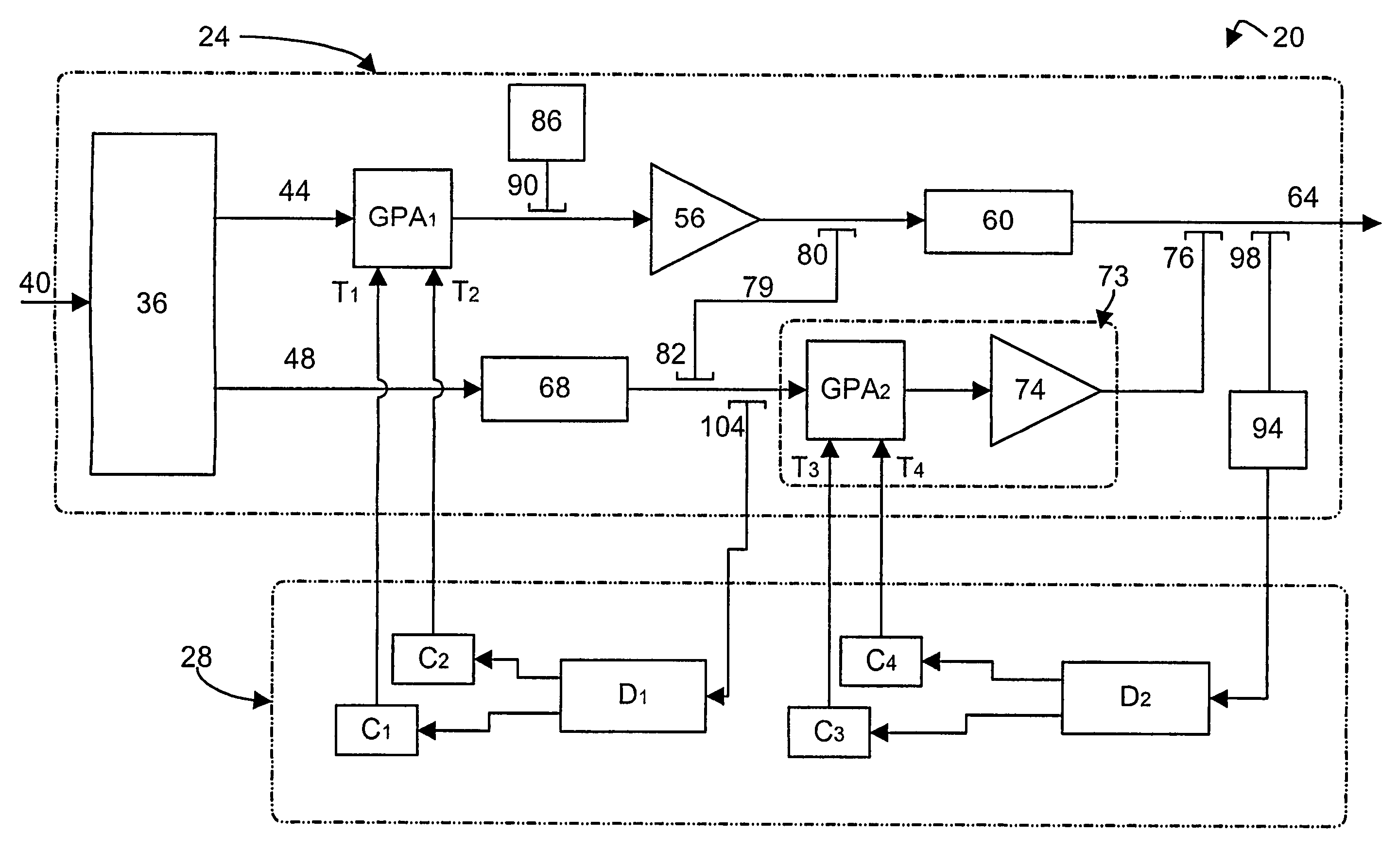
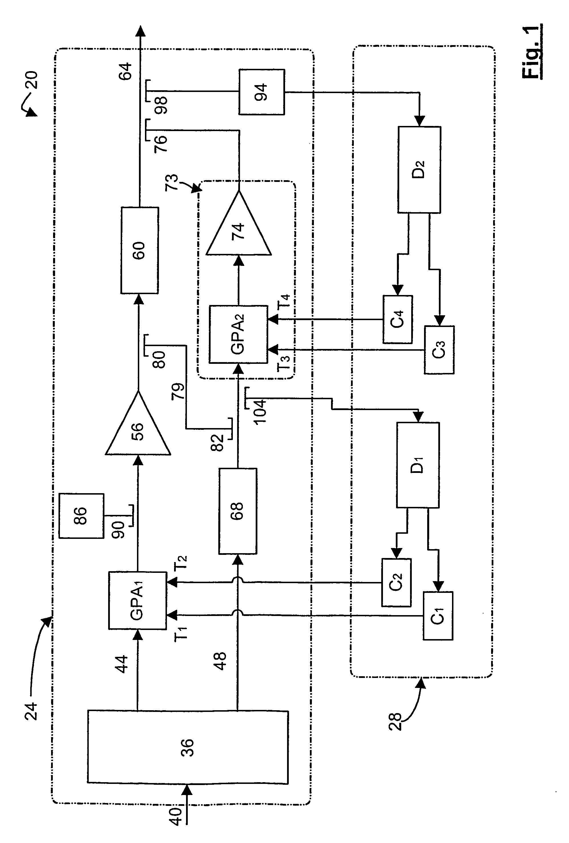
[0057]Referring now to FIG. 1, a forward feed amplifier (“FFA”) in accordance with an embodiment of the invention is indicated generally at 20. FFA 20 comprises an amplifier portion 24 and a detector-controller portion 28. Amplifier portion 24 includes a coupler 36 that is connected to an input signal path 40. Coupler 36 is operable to split an incoming signal from path 40 into a main amplifier signal path 44 and a correctional amplifier signal path 48.

[0058]Main amplifier signal path 44, which carries the main signal from coupler 36, includes a gain and phase adjuster GPA1, a main amplifier 56 and a delay element 60 that outputs to an output signal path 64. GPA1 includes a gain control input tap T1, and a phase control input tap T2, each of which can be steered so that GPA1 operates to yield maximum signal cancellation at the output of coupler 82 and the input of coupler 104, as discussed below. The location in the circuit at which maximum signal cancellation is to occur is sometim...


PUM


Abstract

A feed-forward amplifier having a signal cancellation loop including a cancellation node that includes a gain controller and a phase controller. Each controller provides a discrete tap steering signal and modulates the corresponding tap steering signal with a discrete tracer signal that takes on a preselected sequence of values. The sequence chosen so that the tracer signal is mutually orthogonal to each other tracer signal over a preselected period. A gain and phase adjuster connected to the outputs of the controllers provides a controlled gain change and phase shift in the signal cancellation loop, the magnitude of the gain change and phase shift controlled by the corresponding tap steering signals presented to the gain and phase adjuster by the controllers. A detector, the input of which is connected to the cancellation node and the output of which is connected to the controllers, outputs a measure of the envelope of the signal at the cancellation node. After the preselected period new values for the tap steering signals presented to the gain and phase adjuster by the controllers are obtained by multiplying detector output by the respective tracer signal, each over the respective preselected period, summing each resulting series of values, and changing the tap steering signals to be modulated and presented to the gain and phase adjuster in accordance with the values of the respective sums.

Description

PRIORITY CLAIM[0001]The present application claims priority from each of U.S. provisional patent application No. 60 / 311,358, filed Aug. 13, 2001 and from U.S. non-provisional patent application Ser. No. 10 / 016,691, filed Dec. 17, 2001, the contents of both of which are incorporated herein by reference.FIELD OF THE INVENTION[0002]The present invention relates to adaptive circuits. More specifically, the present invention relates to an apparatus and method for controlling adaptive circuits, such as controlling gain and phase adjustments in a feed forward amplifier circuit.BACKGROUND OF THE INVENTION[0003]Adaptive circuits are well known and used in a variety of applications. One well-known example of an adaptive circuit is the feed forward amplifier (“FFA”). In order to achieve linearity in a feed forward amplifier, careful control of the amplifier circuitry is required. In particular, in FFAs two or more gain and phase adjusters are often employed and the taps of each of these adjust...

Claims


Application Information

Patent Timeline
Patent Type & Authority Patents(United States)
IPC IPC(8): H03F1/26H03F1/32H03G3/30
CPCH03F1/3235H03F2201/3212
Inventor BLODGETT, JAMES R.
Owner TAIWAN SEMICON MFG CO LTD
Why Eureka
Try Eureka