
Light diffusing film

Inactive Publication Date: 2007-05-15
SKC HI TECH & MARKETING CO LTD CO REGISTRATION NO 161511 0225312
View PDF8 Cites 34 Cited by
  • Summary
  • Abstract
  • Description
  • Claims
  • Application Information

AI Technical Summary

Benefits of technology

[0010]To solve the above-described problems, it is an object of the present invention to provide a light diffusing film having excellent luminance uniformity while exhibiting no partial deterioration in light transmittance and generating no black spots.

Problems solved by technology

In particular, since a picture display device, unlike a cathode ray tube, adopts an indirect illumination system in which light irradiated from a fluorescent tube of a backlight provided on the backside of the device is reflected to a metal deposition layer or semi-transparent or opaque, white reflecting plate to display a picture through a light guide plate, visibility is poor, which becomes worsened according to pursuit of larger display devices.
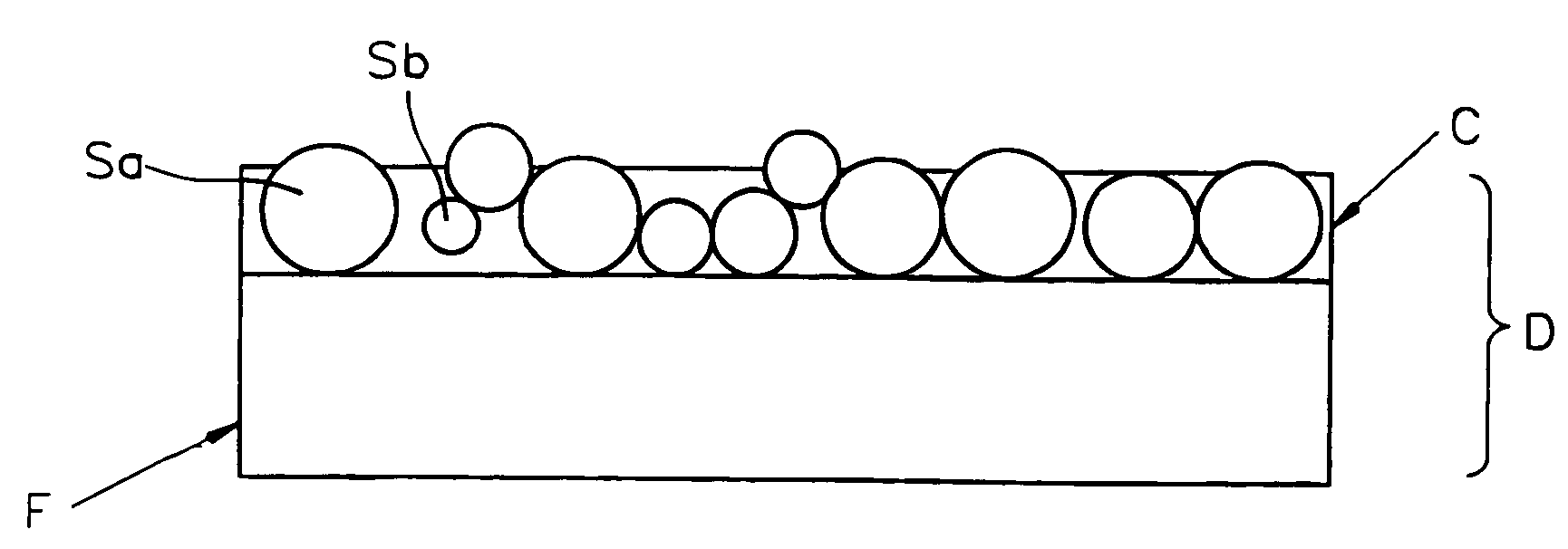
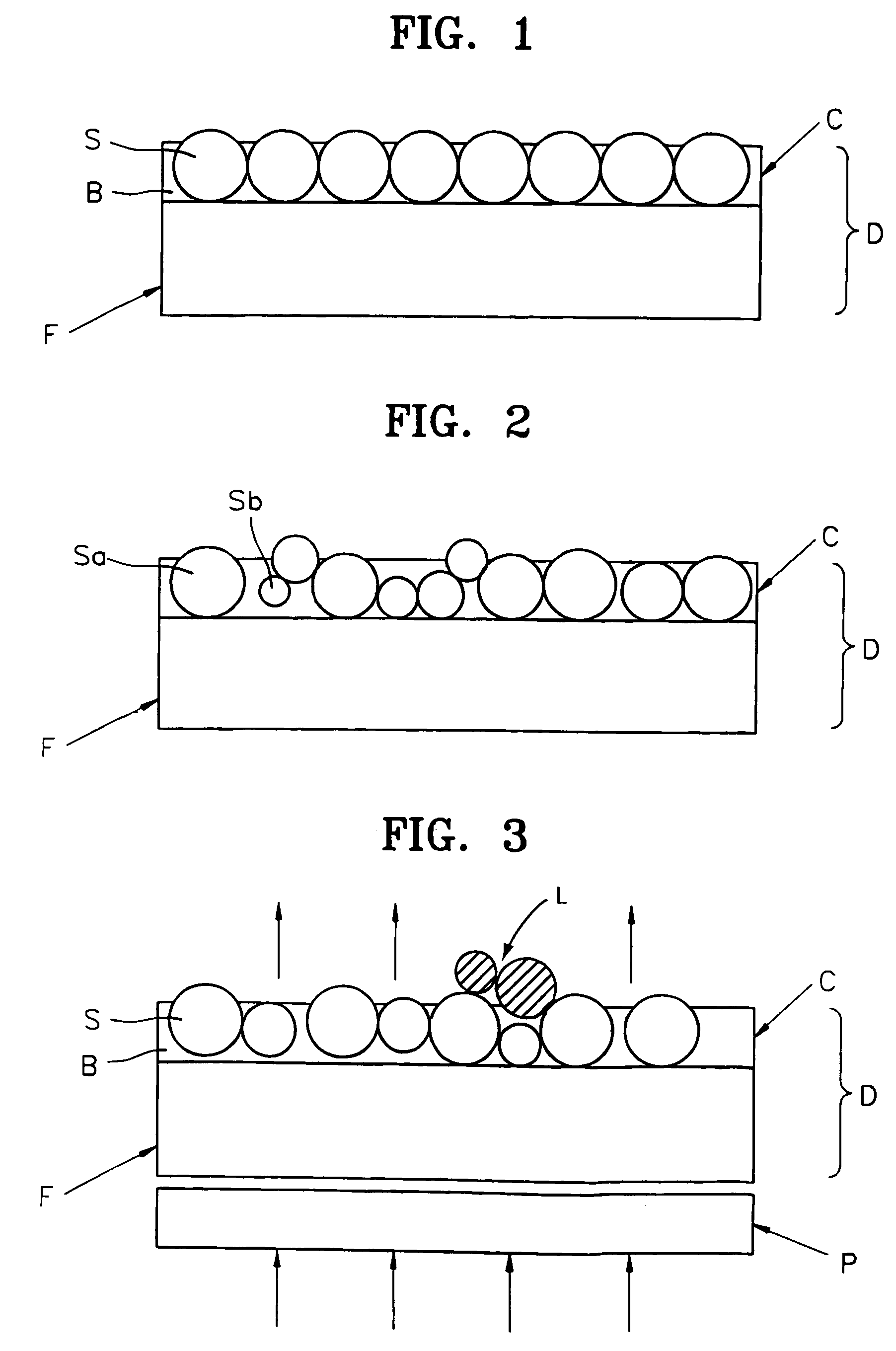
However, in such a light diffusing layer, light diffusing materials cannot exist independently but flocculate with one another or exist in the form of laminates.
Thus, there is a limit in improving the uniformity in luminance.
Also, black spots are easily visible by naked eye, which makes the conventional light diffusing film unsuitable as a light diffusing film.

Method used


Image

  • Light diffusing film
  • Light diffusing film
  • Light diffusing film

Examples


example 1

[0032]A light diffusing composition having the following constituents was coated on a 100 μm thick PET film (Model No. SH31 of SKC Co., Ltd., Korea) at a dose of 15 g / m2 using a 0.3 mm myer bar and dried at 120° C. for 3 minutes, thereby manufacturing a light diffusing film having a lamination ratio of 1.2% and a flocculated particle diameter of 20 μm. Then, the black spots and luminance characteristic of the manufactured light diffusing film were evaluated, and the results thereof are listed in Table 1.

[0033]

Binder resin25.4 parts by weight(Nipporan 125, Nippon Polyurethane Co.)Curing agent2.9 parts by weight(Coronate HX, Nippon Polyurethane Co.)Monodisperse polymethylmethacrylate light diffuser30.3 parts by weight(MX-1000 having an average particle diameter of10 μm, Soken Chemical Co., Ltd.)Solvent41.4 parts by weight(MEK:toluene = 1:1)

example 2

[0034]A light diffusing film having a lamination ratio of 2.7% and a flocculated particle diameter of 25 μm was prepared from the following composition by the same equipment and method as in Example 1. Then, the black spots and luminance characteristic of the prepared light diffusing film were evaluated, and the results thereof are listed in Table 1.

[0035]

Binder resin25.4 parts by weight(Nipporan 125, Nippon Polyurethane Co.)Curing agent2.9 parts by weight(Coronate HX, Nippon Polyurethane Co.)Monodisperse polymethylmethacrylate light diffuser21.2 parts by weight(MX-1000 having an average particle diameter of10 μm, Soken Chemical Co., Ltd.)Monodisperse polymethylmethacrylate light diffuser21.2 parts by weight(MX-500 having an average particle diameter of5 μm, Soken Chemical Co., Ltd.)Solvent41.4 parts by weight(MEK:toluene = 1:1)

example 3

[0036]A light diffusing film having a lamination ratio of 0.8% and a flocculated particle diameter of 30 μm was prepared from the following composition by the same equipment and method as in Example 1. Then, the black spots and luminance characteristic of the prepared light diffusing film were evaluated, and the results thereof are listed in Table 1.

[0037]

Binder resin25.4 parts by weight(Nipporan 125, Nippon Polyurethane Co.)Curing agent2.9 parts by weight(Coronate HX, Nippon Polyurethane Co.)Monodisperse polymethylmethacrylate light diffuser30.3 parts by weight(MX-1500 having an average particle diameter of15 μm, Soken Chemical Co., Ltd.)Solvent41.4 parts by weight(MEK:toluene = 1:1)


PUM


Abstract

A light diffusing film which is excellent in luminance uniformity and which exhibits no partial deterioration in light transmittance, thereby eliminating the formation of black spots. The light diffusing film, which has a monodisperse light diffuser and a light diffusing layer consisting of a light diffuser and a binder resin on one plane of a base, in which the lamination ratio is 10% or less and the diameter of flocculated particles in the light diffuser is 50 μm or less, exhibits excellent luminance and thermal properties, so that it can be suitably used in various kinds of picture display devices, in particular, in a display device employing LED (light emitting diode) lamps or an LCD (liquid crystal display device) backlight system.

Description

TECHNICAL FIELD[0001]The present invention relates to a light diffusing film, and more particularly, to a light diffusing film which is excellent in luminance uniformity and which exhibits no partial deterioration in light transmittance, thereby eliminating the formation of black spots.BACKGROUND ART[0002]In industry, polymeric resin films have a wide variety of applications including bases for packing, photographic films, condensers, electric insulators, labels, magnetic recording media, medical purposes. In recent years, polymeric resin films have also been in widespread use as base materials for picture display devices such as rear projection type screens, plasma display panels or liquid crystal display devices.[0003]In particular, since a picture display device, unlike a cathode ray tube, adopts an indirect illumination system in which light irradiated from a fluorescent tube of a backlight provided on the backside of the device is reflected to a metal deposition layer or semi-t...

Claims


Application Information

Patent Timeline
IPC IPC(8): G02B5/02F21V8/00F21Y101/02G02F1/1335G02F1/13357
CPCG02B5/0226G02B5/0278Y10T428/25
Inventor AHN, CHEOL HEUNGMOON, CHI UK
Owner SKC HI TECH & MARKETING CO LTD CO REGISTRATION NO 161511 0225312
Learn More