Endoscope objective lens

a technology of objective lens and endoscope, which is applied in the field of endoscope objective lens, can solve the problems of insufficient correction of astigmatism, increased manufacturing cost, and impaired processibility, and achieve good optical performance

Active Publication Date: 2007-05-15
FUJI PHOTO OPTICAL CO LTD
View PDF7 Cites 57 Cited by
  • Summary
  • Abstract
  • Description
  • Claims
  • Application Information

AI Technical Summary

Benefits of technology

[0008]The present invention was made considering the situation, and has an objective of providing an endoscope objective lens which has a lens constitution of a relatively small number of three pieces, a short total length of lens, and various kinds of good optical performances starting with correction of curvature of field.

Problems solved by technology

However, there was a problem that it was difficult to suppress coma and astigmatism in this objective lens unless an aspheric lens was used, which impaired processibility and increased manufacturing cost.
H9-68647 is the one which has a three-piece constitution of negative, positive, and positive from the object side, and is short in total lens length, there was a problem that correction of astigmatism was insufficient.
However, in the technology described in this publication document, sufficient consideration is not always given in the respect of the correction of curvature of field, thus an endoscope objective lens of higher performance has been demanded by the actual field of medical practices.

Method used


Image

  • Endoscope objective lens
  • Endoscope objective lens
  • Endoscope objective lens

Examples


example 1

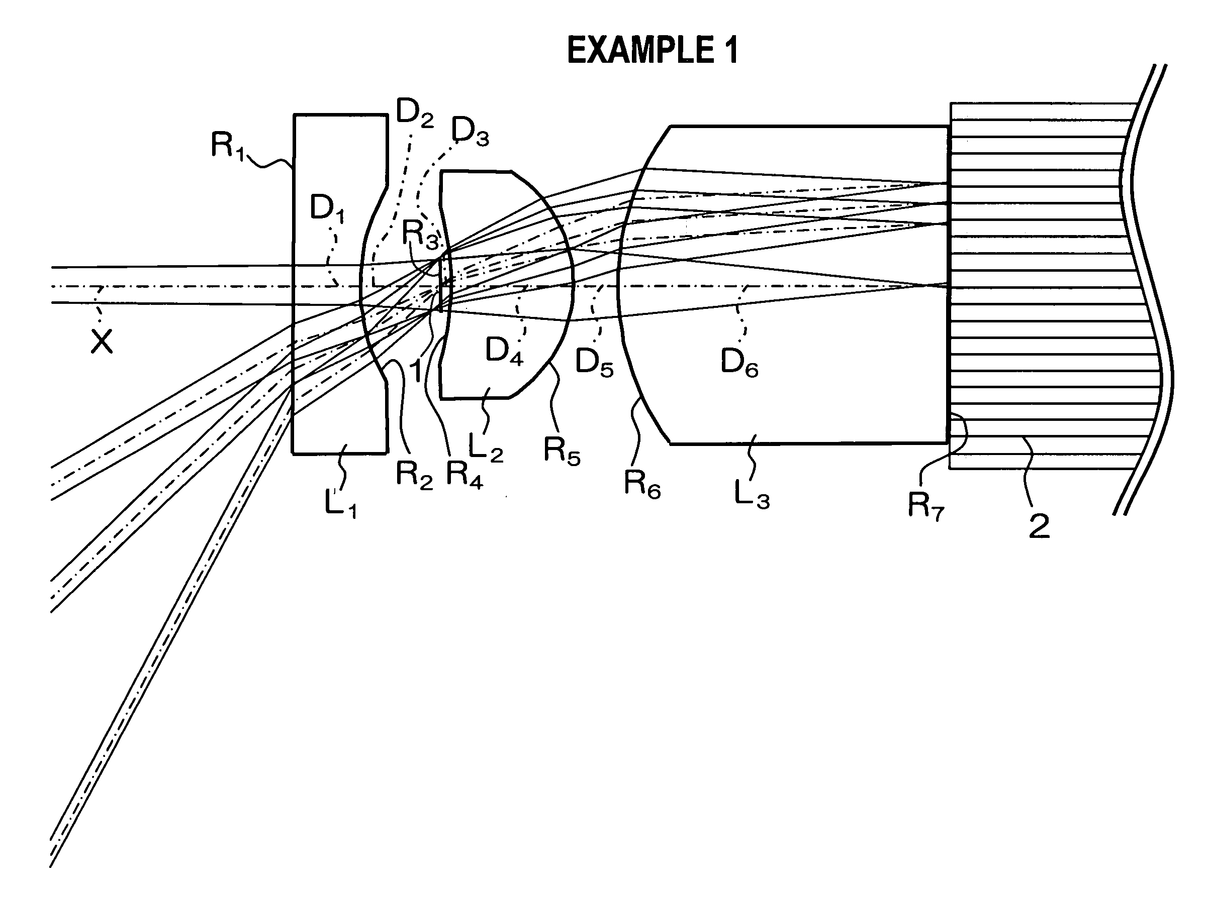
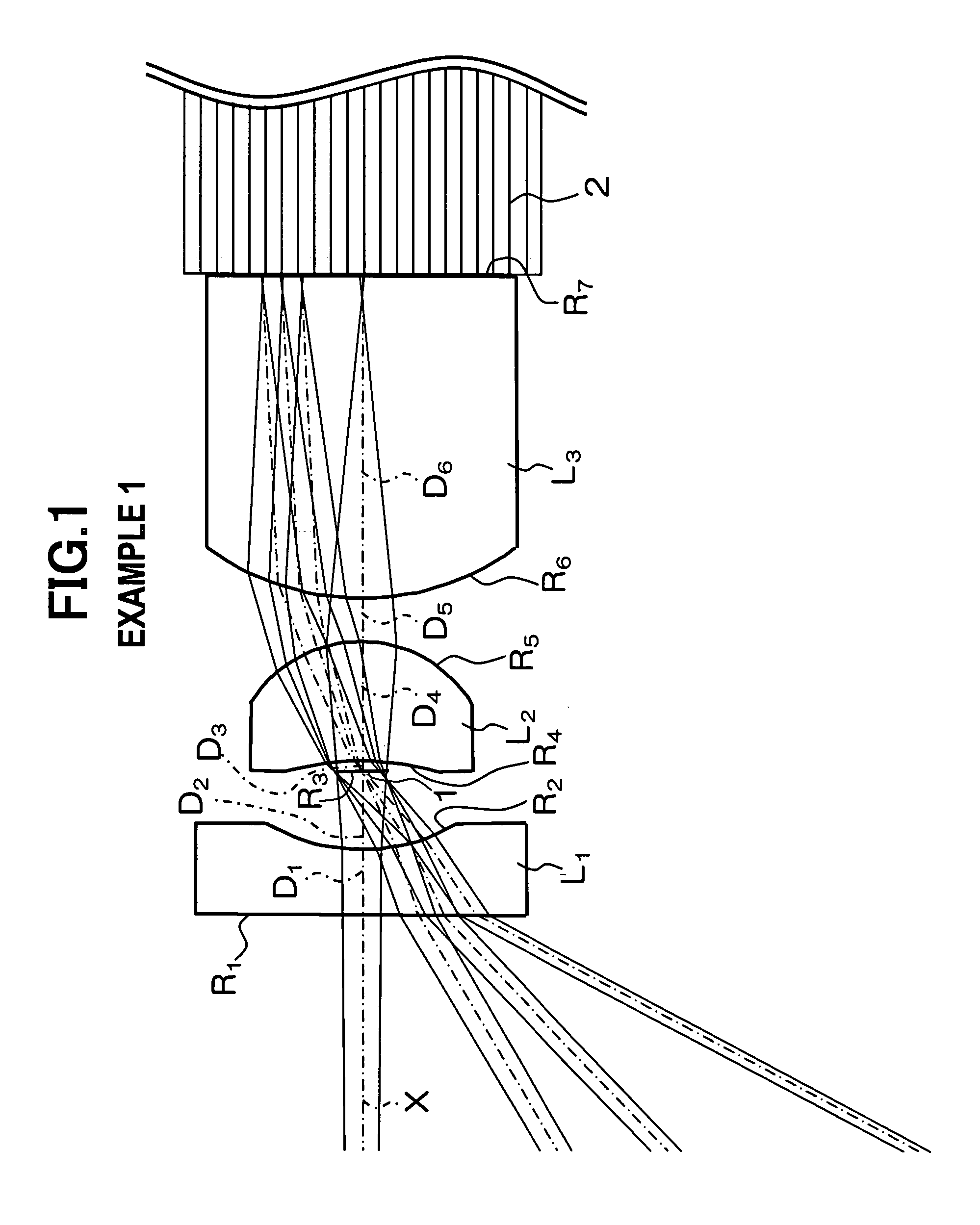
[0050]The schematic constitution of an endoscope objective lens of Example 1 is shown in FIG. 1. In this endoscope objective lens, a first lens L1 made of a planoconcave lens directing its concave surface to the image side, a second lens L2 made of a positive meniscus lens directing its convex surface to the image side, and a third lens made of a planoconvex lens directing its convex surface to the object side are arranged successively from the object side, and a stop 1 is placed between the first lens L1 and the second lens L2. Note that each lens surface is formed with a spherical or planar surface.

[0051]Radius of curvature R (mm) of each lens surface, center thickness of each lens and air gap between lenses D (mm) (below, these are collectively called as on-axis surface distances), and values of refractive index N and Abbe number ν of each lens at the d line of this endoscope objective lens are listed in Table 1 (follows). Note that numbers in the table indicate the order from th...

example 2

[0054]The schematic constitution of an endoscope objective lens of Example 2 is shown in FIG. 3. The constitution of this endoscope objective lens is also about the same with that of Example 1, thus the same numbers are assigned to the same elements in explaining the corresponding drawings, omitting duplicate explanations.

[0055]Radius of curvature R (mm) of each lens surface, center thickness of each lens and air gap between lenses D (mm), and values of refractive index N and Abbe number ν of each lens at the d line of this endoscope objective lens are listed in Table 2 (follows). Note that numbers in the table indicate the order from the object side (the third surface is a stop). It is clear that on-axis distances are longer in this endoscope objective lens than those in Example 1.

[0056]Also, according to the endoscope objective lens of Example 2, as shown in Table 4 (follows), Conditional Expressions (1) to (4) are all satisfied. Then, total length of the lens system is set to 3.2...


PUM


Abstract

To provide an endoscope objective lens which has a lens constitution of a relatively small number of three pieces, a short total length of lens, and various kinds of good optical performances starting with curvature of field. It is constituted of a first lens L1 directing its concave surface to the image side, a second lens L2 made of a positive meniscus lens directing its convex surface to the image side, and a third lens L3 made of a planoconvex lens directing its convex surface to the object side arranged sequentially from the object side, and a stop placed between said first lens L1 and said second lens L2. It also satisfies the following Conditional Expressions:2.00<|f1 / f|<3.00,  (1)0.50<|f2 / f3|<0.70,  (2)2.00<|f1 / d1-2|<5.00 ,  (3)0.40<|R2R / R2F|<0.60 .  (4)Note that f is the focal length of the whole system, f1–f3 the focal lengths of the first-third lenses, respectively, d1-2 the air distance between the first lens and the second lens, R2F the radius of curvature of the object-side surface of the second lens, and R2R the radius of curvature of the image-side surface of the second lens.

Description

RELATED APPLICATIONS[0001]This application claims the priority of Japanese Patent Application No. 2005-151480 filed on May 24, 2005, which is incorporated herein by reference.BACKGROUND OF THE INVENTION[0002]1. Field of the Invention[0003]The present invention relates to an endoscope objective lens which is placed at the tip section of an endoscope and comprises a compact objective lens.[0004]2. Description of the Prior Art[0005]Conventionally, endoscopes are utilized for places which is difficult to see directly, especially inside human bodies. As its objective lens system, various kinds constituted of multiple lens pieces are known.[0006]Among them, shown in Japanese Unexamined Patent Publication No. H2-176612 for example is the one where the space for focus adjustment is reduced to make the total length of the objective lens shorter. However, there was a problem that it was difficult to suppress coma and astigmatism in this objective lens unless an aspheric lens was used, which i...

Claims


Application Information

Patent Timeline
Patent Type & Authority Patents(United States)
IPC IPC(8): G02B21/02G02B9/12
CPCG02B9/12G02B23/243
Inventor MIYANO, HITOSHI
Owner FUJI PHOTO OPTICAL CO LTD
Why Eureka
Try Eureka