System and method for a hierarchical system management architecture of a highly scalable computing system

a computing system and hierarchical system management technology, applied in the field of computer communication, can solve the problems of increasing overhead burden, diminishing performance and cost returns of system management for scalable parallel processing systems, etc., and achieve the effect of facilitating error-free interconnection

Inactive Publication Date: 2007-05-15
MORGAN STANLEY +1
View PDF4 Cites 23 Cited by
  • Summary
  • Abstract
  • Description
  • Claims
  • Application Information

AI Technical Summary

Problems solved by technology

As the number of computing units in the parallel computing system increases, the overhead communications traffic increases not just geometrically, but in some cases, exponentially, creating increasing overhead burden in which an increasing amount of processing power is used merely by communicating between the computing units, and a proportionately lesser amount of processing power is available to support the application.
Thus, the system management for scalable parallel processing systems have diminishing returns in terms of performance and cost.

Method used


Image

  • System and method for a hierarchical system management architecture of a highly scalable computing system
  • System and method for a hierarchical system management architecture of a highly scalable computing system
  • System and method for a hierarchical system management architecture of a highly scalable computing system

Examples


Embodiment Construction

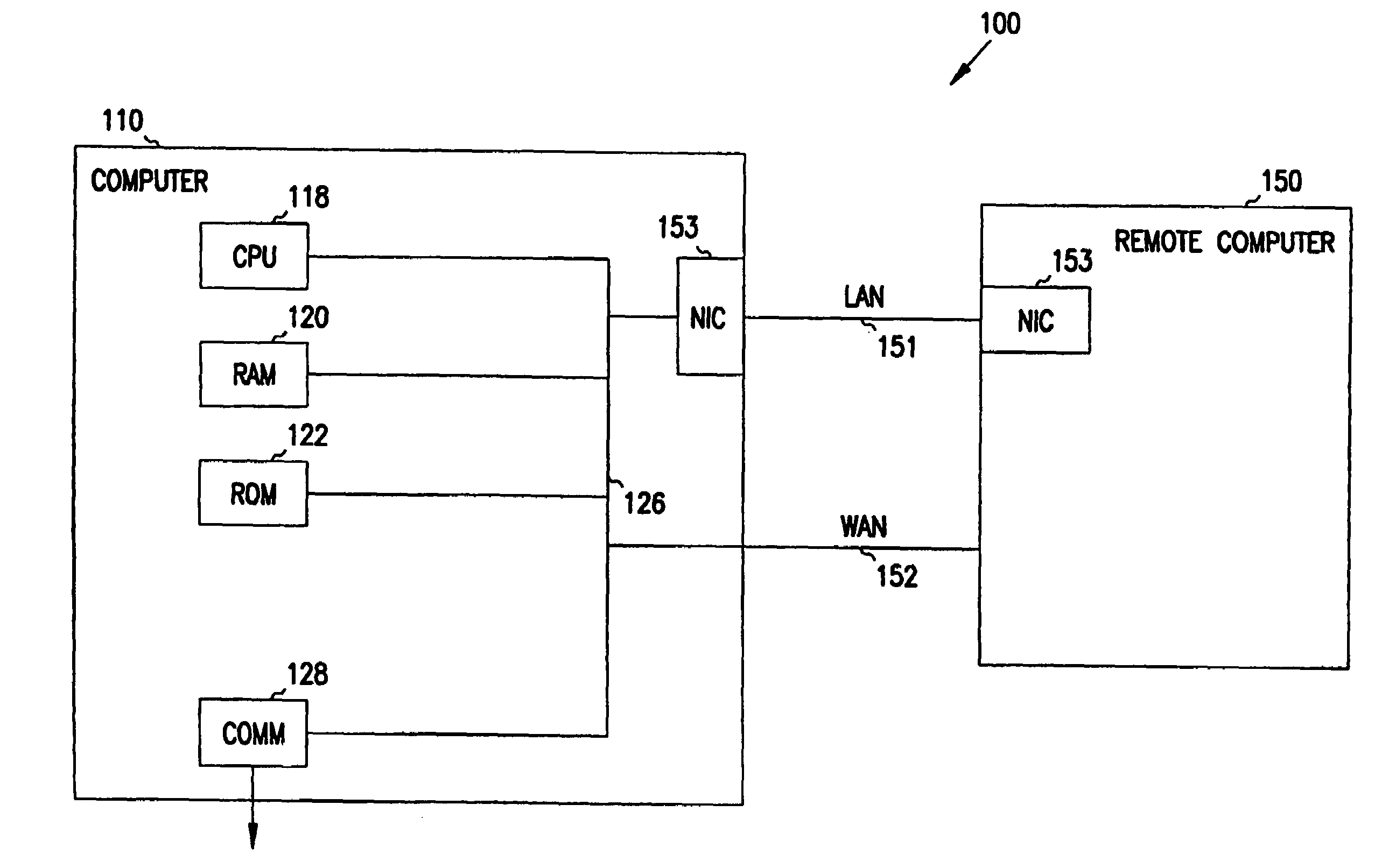
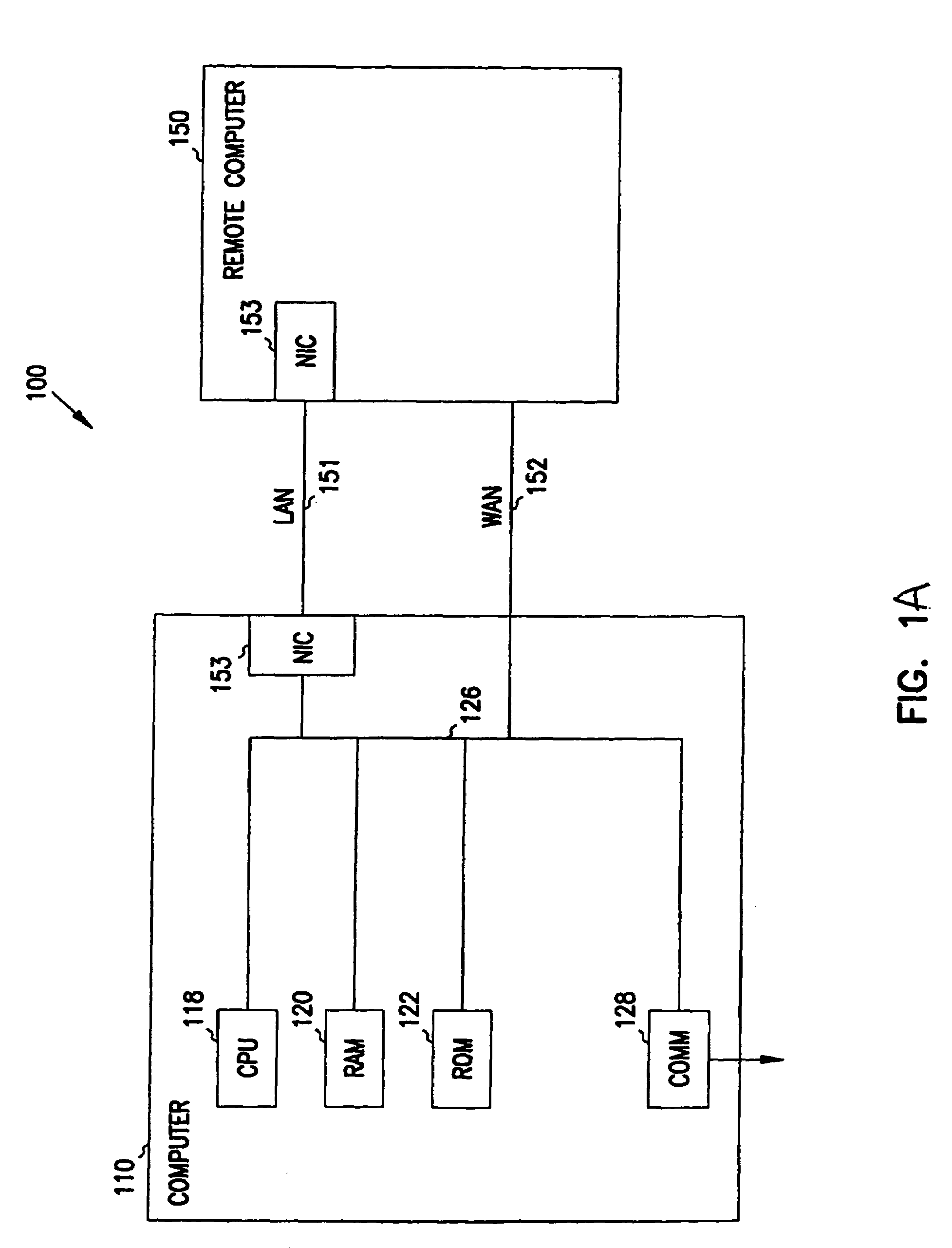
[0026]In the following detailed description of exemplary embodiments of the invention, reference is made to the accompanying drawings which form a part hereof, and in which is shown by way of illustration specific exemplary embodiments in which the invention may be practiced. These embodiments are described in sufficient detail to enable those skilled in the art to practice the invention, and it is to be understood that other embodiments may be utilized and that logical, mechanical, electrical and other changes may be made without departing from the scope of the present invention. The following detailed description is, therefore, not to be taken in a limiting sense, and the scope of the present invention is defined only by the appended claims.

[0027]The detailed description is divided into five sections. In the first section, the hardware and the operating environment in conjunction with which embodiments of the invention may be practiced are described. In the second section, a syste...


PUM


Abstract

A modular computer system includes at least two processing functional modules each including a processing unit adapted to process data and adapted to input / output data to other functional modules through at least two ports with each port including a plurality of data lines. At least one routing functional module is adapted to route data and adapted to input / output data to other functional modules through at least two ports with each port including a plurality of data lines. At least one input or output functional module is adapted to input or output data and adapted to input / output data to other functional modules through at least one port including a plurality of data lines. Each processing, routing and input or output functional module includes a local controller adapted to control the local operation of the associated functional module, wherein the local controller is adapted to input and output control information over control lines connected to the respective ports of its functional module. At least one system controller functional module is adapted to communicate with one or more local controllers and provide control at a level above the local controllers. Each of the functional modules adapted to be cabled together with a single cable that includes a plurality of data lines and control lines such that control lines in each module are connected together and data lines in each unit are connected together. Each of the local controllers adapted to detect other local controllers to which it is connected and to thereby collectively determine the overall configuration of a system.

Description

CROSS-REFERENCE TO RELATED APPLICATIONS[0001]This application is a continuation of U.S. patent application Ser. No. 09 / 407,429 filed Sep. 29, 1999 now abandoned, a continuation of U.S. patent application Ser. No. 09 / 425,122 filed Oct. 22, 1999 now abandoned, and a continuation of U.S. patent application Ser. No. 09 / 422,745 filed Oct. 22, 1999 now abandoned.FIELD OF THE INVENTION[0002]This invention relates generally to computer communications, and more particularly to control and communication of highly scalable and massively parallel computing systems.COPYRIGHT NOTICE / PERMISSION[0003]A portion of the disclosure of this patent document contains material which is subject to copyright protection. The copyright owner has no objection to the facsimile reproduction by anyone of the patent document or the patent disclosure as it appears in the Patent and Trademark Office patent file or records, but otherwise reserves all copyright rights whatsoever. The following notice applies to the sof...

Claims


Application Information

Patent Timeline
Patent Type & Authority Patents(United States)
IPC IPC(8): G06F15/16G06F15/173G06F3/00
CPCG06F11/30G06F11/3006G06F11/3048G06F11/3051G06F11/3055G06F11/3058
Inventor BROWN, MICHAELHEIN, STEVEN
Owner MORGAN STANLEY
Why Eureka
Try Eureka