Transfer device for cylindrical stacks of products arranged on an edge

a technology of transfer device and product, which is applied in the direction of conveyors, stacking articles, conveyor parts, etc., can solve the problems of biscuit packaging, limitation of the maximum speed achievable, and the necessity of calibrating the system

Inactive Publication Date: 2007-05-22
PFM
View PDF20 Cites 11 Cited by
  • Summary
  • Abstract
  • Description
  • Claims
  • Application Information

AI Technical Summary

Benefits of technology

[0023]According to a preferred aspect of the present invention, the method envisages that the gripping assembly withholds each stack along at least two surfaces of the stack itself, so as to maintain the stack coherent during the transfer process, and that said assembly may rotate in a motion of rotation about one of its axes and translate along this latter axis in a motion of moving away and approaching with respect to the stacks to enable the required picking-up of each stack from the conveyor set upstream and the positioning of said stack on the conveyor set downstream.

Problems solved by technology

In the first place, the oven-baked products of small thickness, owing to their somewhat brittle nature, in the passage, in general by gravity, from the top belt to the bottom one may get broken or chipped, with the consequent production of packets of biscuits that are not suitable for the market.
Moreover, for the biscuits to fall exactly into the seats (sockets) provided, it is necessary to synchronize carefully the speed of advance of the top belt with that of the bottom conveyor belt, this generally involving both a limitation of the maximum speed achievable, and the necessity of calibrating the system with a certain frequency.
Furthermore, the CAVANNA plant does not enable alternative geometrical dispositions of the top conveyor belt with respect to the bottom belt, other than the arrangement at right angles envisaged, above all if in said plant it is intended to use products conveyed on their edges.
The SIG transfer device, however, does not envisage that the conveyor set downstream causes the stacks to advance in a direction parallel to their axis, and hence does not enable orientation of the stacks in a different way with respect to the direction of advance in the passage from the conveyor set upstream to the conveyor set downstream.
Furthermore, the impossibility of orientation of the stacks during transfer, as well as the geometry itself of the SIG transfer device, enables either only intermittent or else perfectly synchronized operation of the equipment.

Method used


Image

  • Transfer device for cylindrical stacks of products arranged on an edge
  • Transfer device for cylindrical stacks of products arranged on an edge
  • Transfer device for cylindrical stacks of products arranged on an edge

Examples


Embodiment Construction

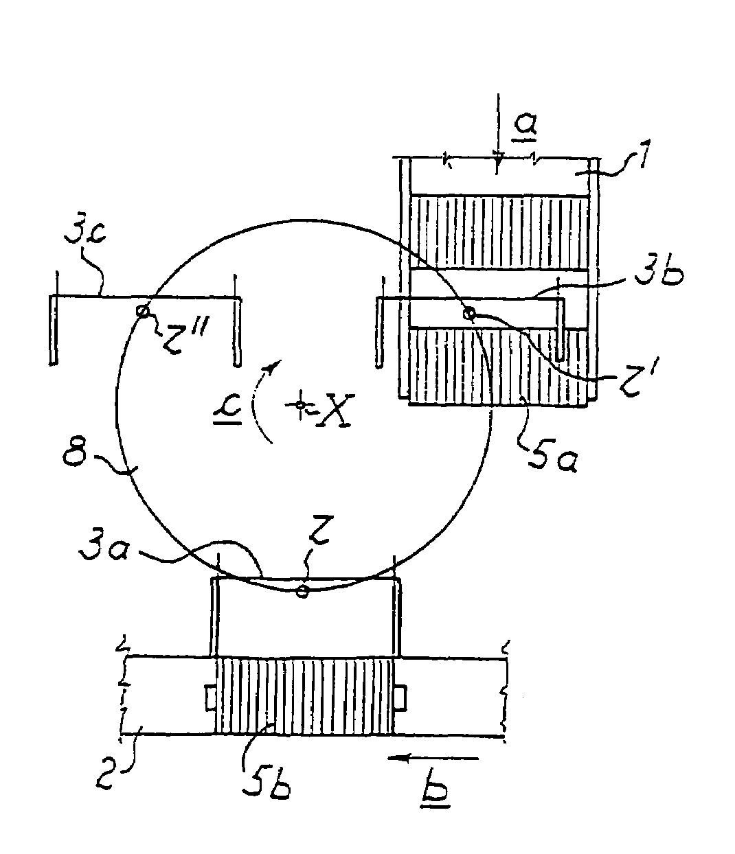
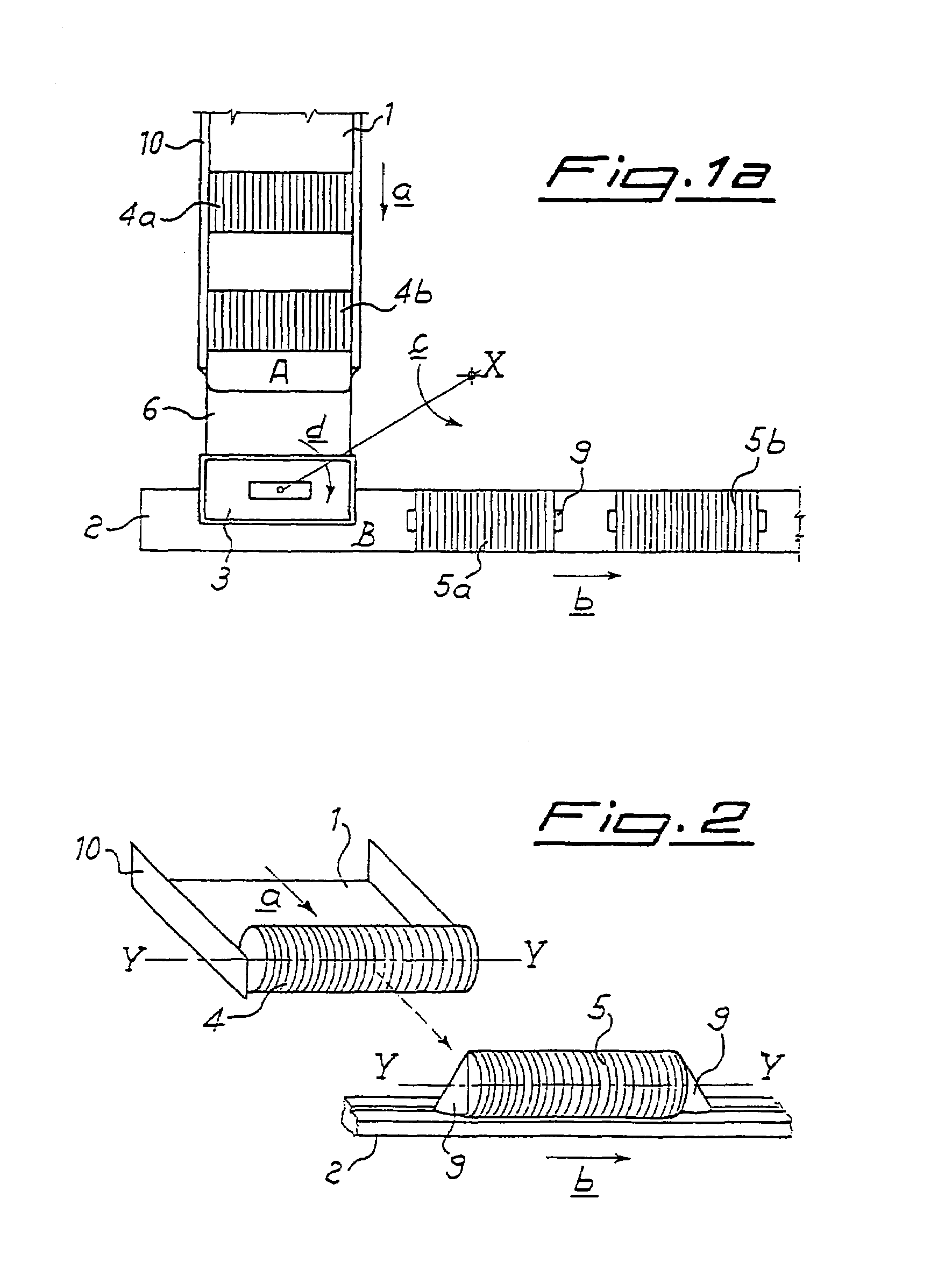
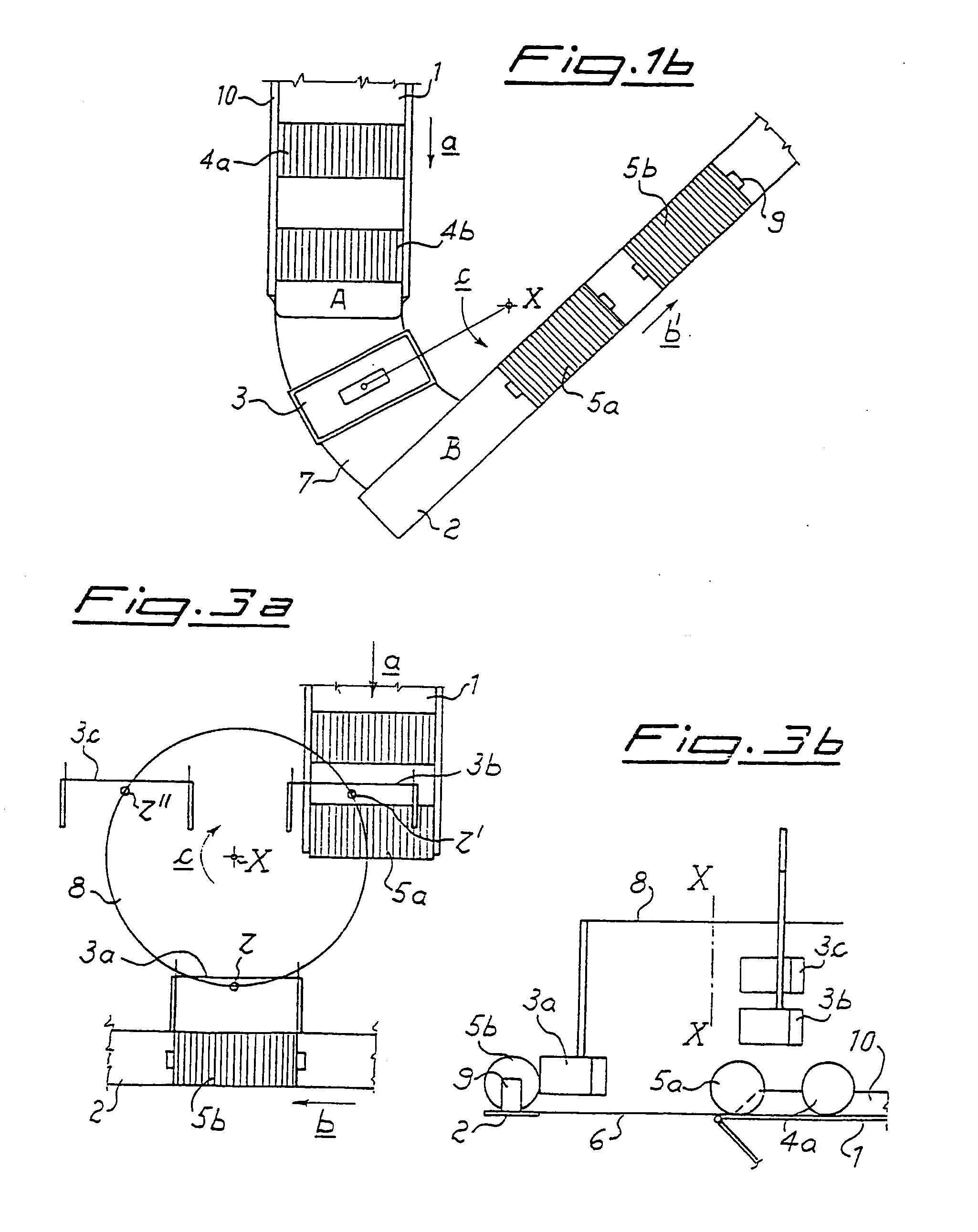
[0040]With reference to FIGS. 1a and 1b, two embodiments of equipment are illustrated, according to the present invention, for the conveying of cylindrical stacks of foodstuff products of small thickness resting on one of their edges, comprising a conveyor set upstream 1, in which the stacks are caused to advance in a direction a orthogonal to the generatrices of the cylindrical stack, a conveyor set downstream 2, in which the stacks are conveyed in a direction b parallel to said generatrices, and an orbital transfer device for transferring the stacks from the conveyor set upstream 1 to the conveyor set downstream 2. FIG. 2 schematically illustrates, by way of example, the spatial disposition of the cylindrical stacks with respect to their directions of advance a and b in the two conveyors 1, 2.

[0041]It is to be noted that, in the attached figures, identical reference numbers indicate identical parts of the equipment and / or of the transfer device.

[0042]The orbital transfer device re...


PUM


Abstract

A transfer device for transferring stacks (4, 4a, 4b, 5, 5a, 5b), which have a cylindrical external shape, of products resting on one of their edges between a conveyor (1) set upstream for advance of the stacks (4, 4a, 4b, 5, 5a, 5b) in a direction (a) transverse to the generatrices of the aforesaid cylindrical shape, and a conveyor (2) set downstream for advance of the stacks In a direction parallel to said generatrices, or vice versa, the said transfer device being operatively set between said conveyor (1) set upstream and said conveyor (2) set downstream. The transfer device comprises at least one gripping assembly (3) for picking up and conveying a stack. Said gripping assembly (3) moreover turns, according to a motion of revolution. (C) about a first axis (X), between a position in which it engages a stack (4, 4a, 4b, 5, 5a, 5b), in a position (A) corresponding to an output end of the conveyor (1) set upstream, and a position (B) in which it releases the stack onto the conveyor (2) set downstream.

Description

TECHNICAL FIELD OF THE INVENTION[0001]The present invention relates to a transfer device and a method for the transfer of stacks, which have an external cylindrical shape, of oven-baked products resting on one of their side surfaces (edges) from a conveyor in which the stacks are conveyed in a direction transverse to the generatrices of the cylindrical shape to a conveyor in which the stacks are conveyed in a direction parallel to the generatrices of said cylindrical shape.[0002]In particular, the present invention relates to a device capable of transferring cylindrical stacks of oven-baked products from a conveyor in which said stacks are caused to advance in a direction orthogonal to their own longitudinal axis to a conveyor in which the stacks are caused to advance in a direction parallel to their own longitudinal axis, until they reach packaging equipment for wrapping thereof.[0003]By “stack of oven-baked products of small thickness” is meant a stock formed by foodstuffs baked i...

Claims


Application Information

Patent Timeline
Patent Type & Authority Patents(United States)
IPC IPC(8): B65B23/12B65B23/14B65B35/46B65G47/52B65G47/86B65G47/90
CPCB65B23/14B65B35/46B65G47/52B65G47/847B65G47/902
Inventor CERUTTI, GIULIANOMENEGALDO, PIERREBARBERIS-ORGANISTA, FILIPPO
Owner PFM
Why Eureka
Try Eureka