Fuel conversion reactor

a fuel conversion reactor and fuel technology, applied in the direction of gas-gas reaction process, physical/chemical process catalyst, lighting and heating apparatus, etc., can solve the problem of less hydrogen per molecule of hydrogen-containing fuel, external heat may be required to drive the reaction forward, and low carbon monoxide toleran

Active Publication Date: 2007-05-22
DANA CANADA CORP
View PDF37 Cites 25 Cited by
  • Summary
  • Abstract
  • Description
  • Claims
  • Application Information

AI Technical Summary

Problems solved by technology

One difficulty with steam reformation is that external heat may be required to drive the reaction forward to produce hydrogen and carbon monoxide.
Partial oxidation can be performed at high temperatures (about 1200 to 1500° C.) without a catalyst, or can be performed with a catalyst at much lower temperatures, typically about 500 to 800° C. One disadvantage of partial oxidation is that it produces less hydrogen per molecule of hydrogen-containing fuel than steam reformation, since some of the fuel is consumed by oxidation.
This is particularly true for proton exchange membrane (PEM) fuel cells, which have a low tolerance for carbon monoxide.
Regardless of the specific conversion process utilized, significant thermal stresses are exerted on fuel conversion reactors, which can have a detrimental effect on durability.
With such a heat exchanger, the thermal expansion coefficients of the shell and the tubes during operation can cause a differential movement between them.
Excessive movement of this type can cause the tubes to loosen in the tube sheets.
With this known hydrogen generator structure, there can be a thermal expansion problem if the tubes expand at a different rate than the shell as the tubes are apparently rigidly mounted in the tube sheets which in turn are rigidly mounted in the shell.

Method used


Image

  • Fuel conversion reactor
  • Fuel conversion reactor
  • Fuel conversion reactor

Examples


Embodiment Construction

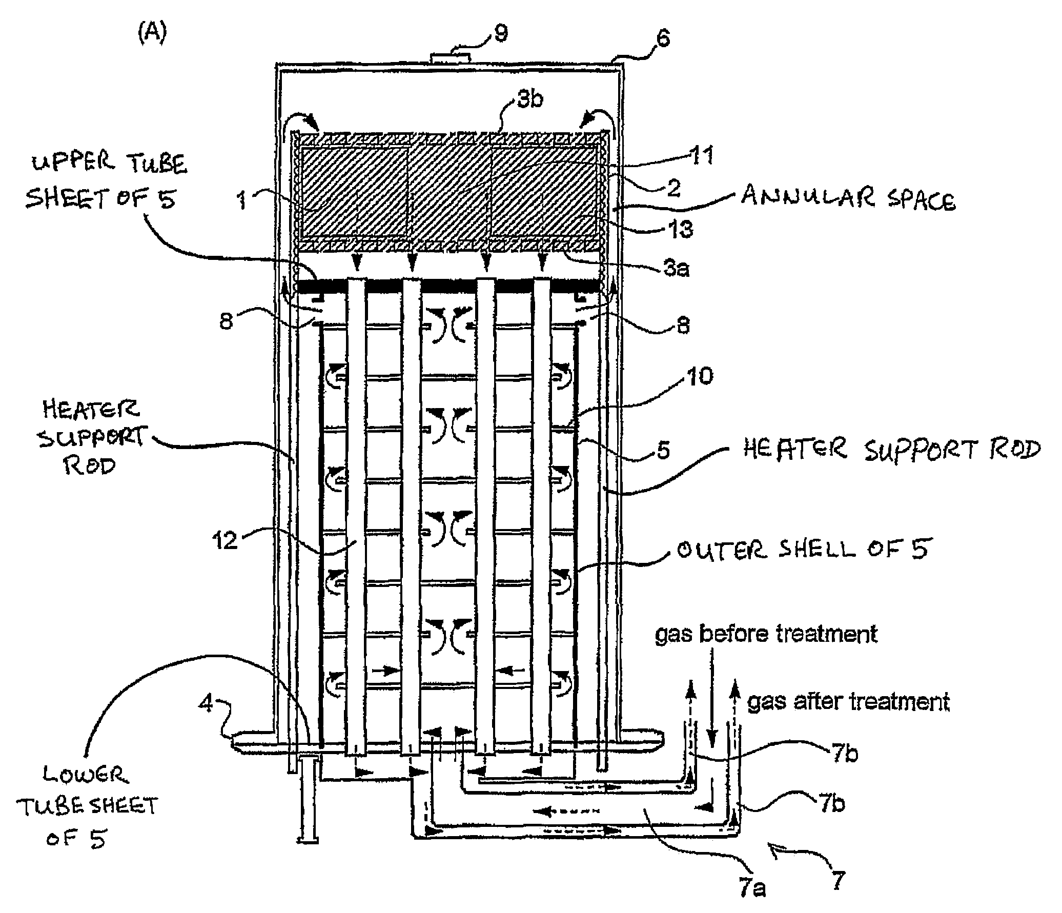
[0036]The preferred fuel conversion reactors according to the invention are described below as fuel reformers. However, it will be appreciated that any of the preferred structures described below may be equally suitable, with minor modifications, for use as catalytic or non-catalytic burners.

[0037]FIG. 1 illustrates a first preferred fuel reformer 10 according to the invention, which is constructed for the purpose of converting hydrogen-containing fuel to hydrogen gas by means of an autothermal reformation process in which a gaseous fluid containing steam and oxygen or an oxygen-containing gas such as air undergoes a catalyzed reaction with a hydrogen-containing fuel. Where the hydrogen-containing fuel comprises a hydrocarbon, the following catalyzed reactions take place in the fuel reformer 10:

(1) Partial Oxidation (Exothermic)

CnHm+n / 2 O2→nCO+m / 2H2

(2) Steam Reformation (Endothermic)

CnHm+nH2O→nCO+(m / 2+n)H2

As mentioned above, the two steps of the autothermal reformation take place in...


PUM

PropertyMeasurementUnit
temperaturesaaaaaaaaaa
gapaaaaaaaaaa

Abstract

A fuel conversion reactor includes a shell-and-tube heat exchanger for controlling the temperature of a hot gaseous mixture produced by catalytic or non-catalytic reaction of a fuel with a gaseous fluid, and for controlling the temperature of the gaseous fluid and / or the fuel prior to the reaction. The reactor is either a catalytic or non-catalytic burner, or a fuel reformer for converting a fuel to hydrogen. A preferred reactor includes an outer shell having first and second ends and an inner surface, a primary inner shell extending into the outer shell, the primary inner shell defining a heat exchanging chamber and having primary and secondary ends, and a secondary inner shell having a first end located adjacent the secondary end of the primary inner shell. One or more outlet apertures are formed between the two inner shells for passage of the gaseous fluid out of the heat exchanging chamber. There are also a plurality of heat exchange tubes extending through the heat exchanging chamber between first and second tube sheets and connected to same. The first tube sheet is mounted in the primary inner shell while the second tube sheet is connected to the secondary inner shell. The tubes form passages for flow of the hot gaseous mixture in heat exchange contact with the gaseous fluid through the heat exchanging chamber, thereby preheating the gaseous fluid prior to reaction with the fuel. The adjacent ends of the inner shells form a disconnected joint and the secondary inner shell is free to move relative to the primary inner shell upon thermal expansion of the tubes.

Description

FIELD OF THE INVENTION[0001]This invention relates to fuel conversion reactors, and more specifically to burners and fuel reformers for use in fuel cell systems.BACKGROUND OF THE INVENTION[0002]The use of fuel cells has become of increasing interest in recent years for the application of power generation by means of a stationary installation and for purposes of transportation where the fuel cell is transported with the vehicle. The fuel of these fuel cells is commonly hydrogen that has been produced by reacting a hydrogen-containing fuel, usually a hydrocarbon or a low molecular weight alcohol, over one or more catalysts in a fuel reformer.[0003]There are a number of known processes for generating hydrogen from hydrogen-containing fuels in a fuel reformer. A first known process for conversion of hydrogen-containing fuels to hydrogen is known as “steam reformation”, which is conducted at elevated temperatures. In the case of a hydrocarbon fuel, steam reformation proceeds via the foll...

Claims


Application Information

Patent Timeline
Patent Type & Authority Patents(United States)
IPC IPC(8): F28D21/00B01J10/00B01J19/00B01J8/00B01J8/02B01J8/04B01J8/06C01B3/34C01B3/38C01B3/48F28D7/16F28F9/02F28F9/22H01M8/0612
CPCB01J8/008B01J8/0242B01J8/0278B01J8/0285B01J8/0453B01J8/048B01J8/0492B01J8/0496B01J8/067C01B3/382C01B3/384C01B3/48F28D7/1607F28D7/1669F28F9/0236F28F9/0241F28F9/22H01M8/0618H01M8/0668B01J2208/00194B01J2208/00221B01J2208/00504B01J2208/0053B01J2208/00849B01J2208/025C01B2203/00C01B2203/0233C01B2203/0244C01B2203/0261C01B2203/0283C01B2203/0288C01B2203/044C01B2203/047C01B2203/066C01B2203/0811C01B2203/0844C01B2203/0883C01B2203/1023C01B2203/1082C01B2203/1217C01B2203/1235C01B2203/1241C01B2203/1247C01B2203/1276C01B2203/1288C01B2203/142C01B2203/1604C01B2203/1685C01B2203/169C01B2203/82Y02E60/522Y02E60/50
Inventor RONG, XIAOYANGCHEADLE, BRIAN E.
Owner DANA CANADA CORP
Why Eureka
Try Eureka