Fastening arrangement of a force-transmitting device

a force-transmitting device and fastening technology, which is applied in the direction of force/torque/work measurement apparatus, measurement devices, instruments, etc., can solve the problems of high manufacturing process cost, stress caused, and measurement errors, and achieve the effect of high degree of structural stability, good degree of uncoupling, and cost-effectiveness

Active Publication Date: 2007-05-22
METTLER TOLEDO GMBH
View PDF14 Cites 14 Cited by
  • Summary
  • Abstract
  • Description
  • Claims
  • Application Information

AI Technical Summary

Benefits of technology

[0013]With this concept, a sufficient depth of material is left in place to connect the fastening part to the rest of the respective parallelogram leg, so that on the one hand the stresses are largely uncoupled from the sensitive part of the force-transmitting device, while on the other hand the force-transmitting device still has a sufficient rigidity to absorb laterally directed torques if they occur, as the entire height as well as the entire width of the respective parallelogram leg are available to intercept such torques. Furthermore, the raised pad areas at the fastening portions ensure well defined fastening zones, so that the contact pressure is evenly distributed and symmetric over the fastening pad surface.

Problems solved by technology

This leads to stresses which are caused on the one hand by cutting the tapped holes in the material that the parallel-guiding mechanism is made of, and on the other hand by tightening the screws in the threaded holes.
As is commonly known, forces and stresses of this kind which come from the mounting attachment can cause errors in the measuring result.
The manufacturing process for the embodiments proposed in EP 0 511 521 B1 is relatively expensive, particularly in the case of the ring-shaped grooves surrounding a fastening location.
This embodiment has the drawback that the structural strength, specifically of the housing-based fixed part and / or of the load-receiving part, suffers as a result of the slot-shaped incisions that run along the entire height or width of the respective parallelogram leg of the force-transmitting device.
In particular, this concept no longer leaves the entire height or width of the respective parallelogram leg available to absorb laterally acting torques.

Method used


Image

  • Fastening arrangement of a force-transmitting device
  • Fastening arrangement of a force-transmitting device
  • Fastening arrangement of a force-transmitting device

Examples


Embodiment Construction

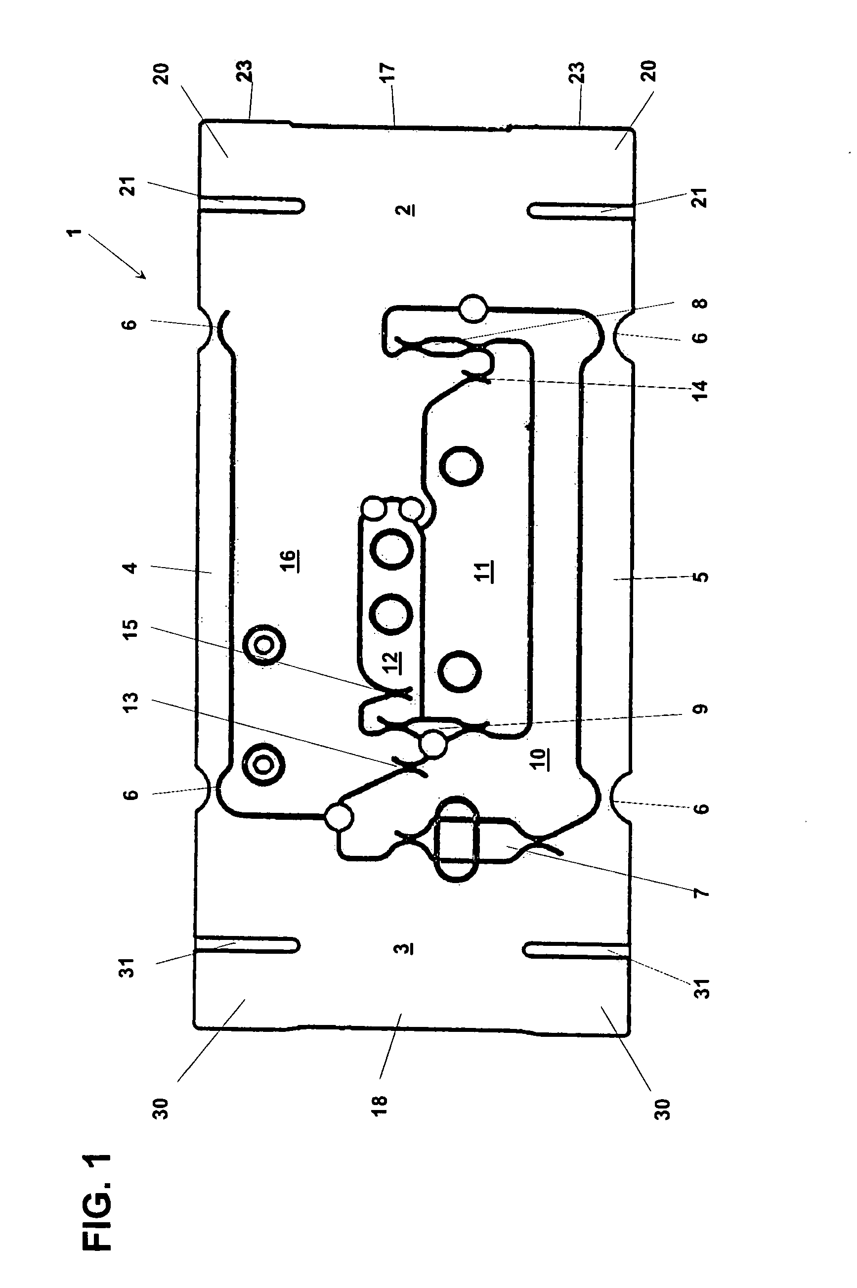
[0031]The force-transmitting device 1 shown in a side view in FIG. 1 is of a type that is used in a force-measuring cell, for example for a weighing scale. This force-transmitting device 1 has a parallel-guiding mechanism with upper and lower parallelogram guides 4 and 5, respectively, each of which is pivotally connected by way of flexure pivots 6 to a vertically movable parallelogram leg 3 and a stationary parallelogram leg 2. The force-transmitting device 1 includes a lever mechanism which in the illustrated arrangement consists of three levers 10, 11, 12. The levers 10, 11, 12 are connected to the vertically movable parallelogram leg 3 and to each other through coupling elements 7, 8, 9 and are pivotally supported by way of fulcrum flexures 13, 14, 15 on a cantilevered extension 16 of the stationary parallelogram leg 2.

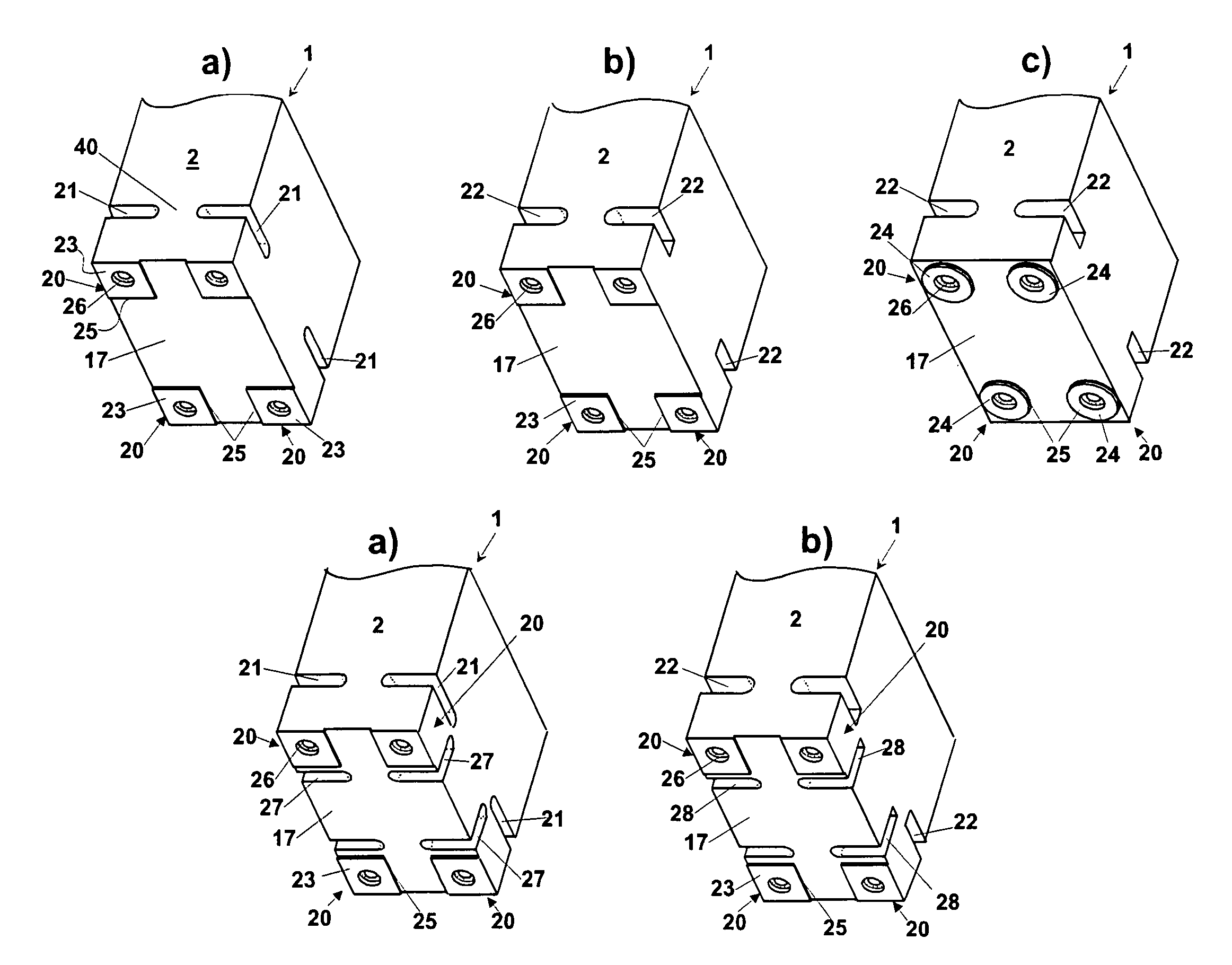
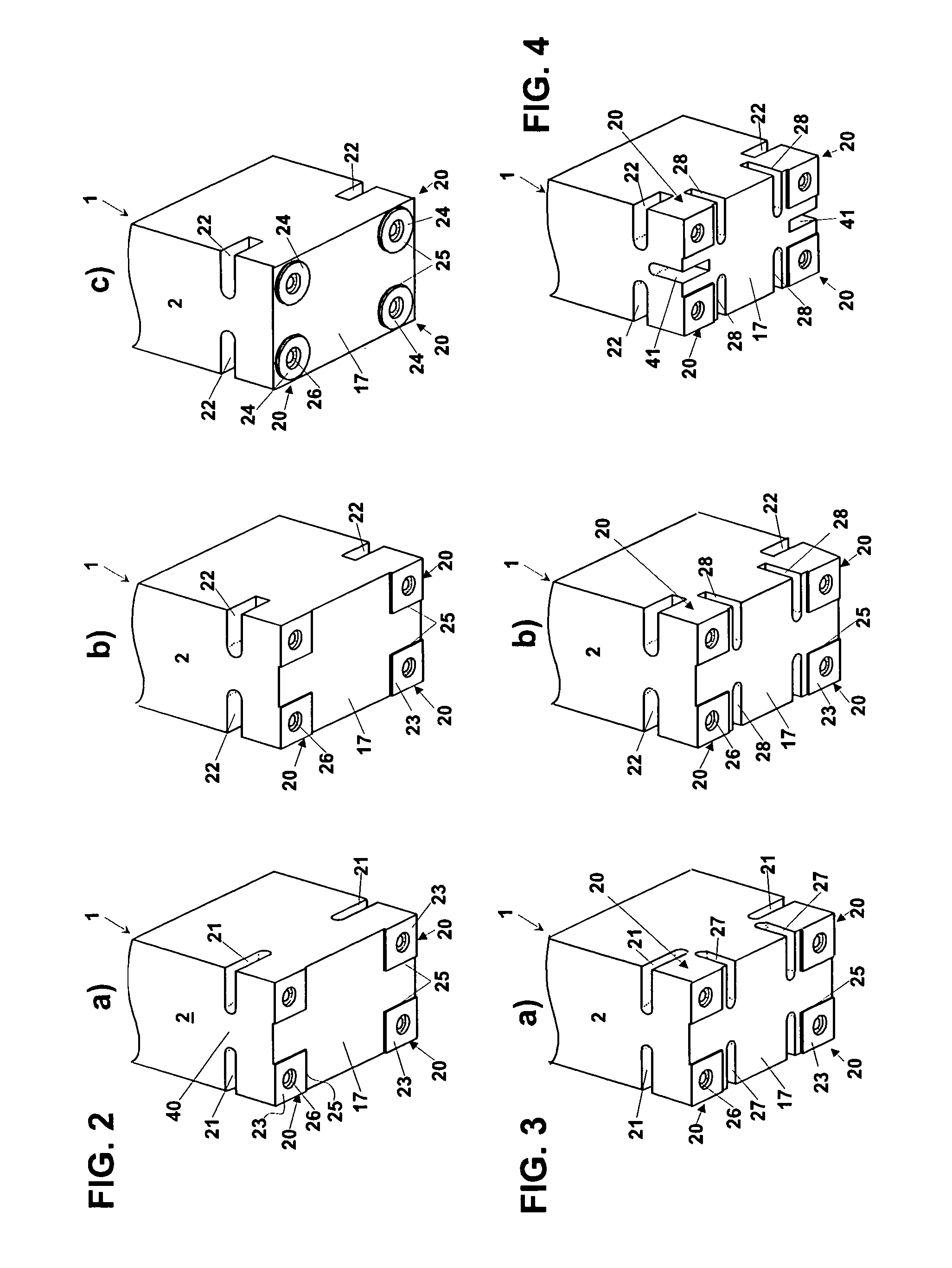
[0032]At the end surface 17 of its stationary parallelogram leg 2, the force-transmitting device 1 has four fastening portions 20 with fastening pad surfaces 23 t...


PUM

PropertyMeasurementUnit
dimensionsaaaaaaaaaa
oblique angleaaaaaaaaaa
circular shapeaaaaaaaaaa

Abstract

In a force-transmitting device of a force-measuring cell with a parallel-guiding mechanism in which a stationary parallelogram leg and a movably guided parallelogram leg are connected to each other by parallelogram guides, each of the parallelogram legs has a fastening part with at least two fastening portions. The fastening portions have fastening pads with tapped holes running perpendicular to the fastening pad surfaces, so that a load carrier can be bolted to the force-transmitting device and / or the device can be fastened to a housing. The parallelogram legs have slot-shaped incisions that serve to uncouple the fastening portions from the rest of the parallelogram leg, so as to prevent the propagation of assembly stresses from the fastening portions into the working parts of the force-measuring cell.

Description

BACKGROUND OF THE INVENTION[0001]The invention relates to a device for transmitting a force in a force-measuring cell with a parallel-guiding mechanism wherein a fixed, stationary parallelogram leg and a movably guided parallelogram leg are connected to each other by parallelogram guides, wherein the stationary parallelogram leg and / or the movably guided parallelogram leg has a part which serves the function of fastening and has at least two fastening portions. Each of the fastening portions has at least one hole running perpendicular to one of the surfaces of the respective parallelogram leg. The holes serve to attach a load carrier to the force-transmitting device and / or to attach the force-transmitting device to a housing or to an intermediate holder. In addition, each of the parallelogram legs has slot-shaped incisions.[0002]The slot-shaped incisions in the fastening part of a parallelogram leg have a stress-uncoupling function, preventing the propagation of a force or stress fr...

Claims


Application Information

Patent Timeline
Patent Type & Authority Patents(United States)
IPC IPC(8): G01G7/00G01G3/12G01G21/24G01L1/22
CPCG01G21/244G01L1/2243
Inventor BURKHARD, HANS-RUDOLF
Owner METTLER TOLEDO GMBH
Why Eureka
Try Eureka