Vacuum prober and vacuum probe method
a vacuum probe and vacuum probe technology, applied in the direction of fault location by increasing the destruction at fault, semiconductor/solid-state device testing/measurement, instruments, etc., can solve the problems of inability to move the table in the x, y and z directions in the vacuum chamber, and the structure of the optical unit is complicated
- Summary
- Abstract
- Description
- Claims
- Application Information
AI Technical Summary
Benefits of technology
Problems solved by technology
Method used
Image

Examples
first embodiment
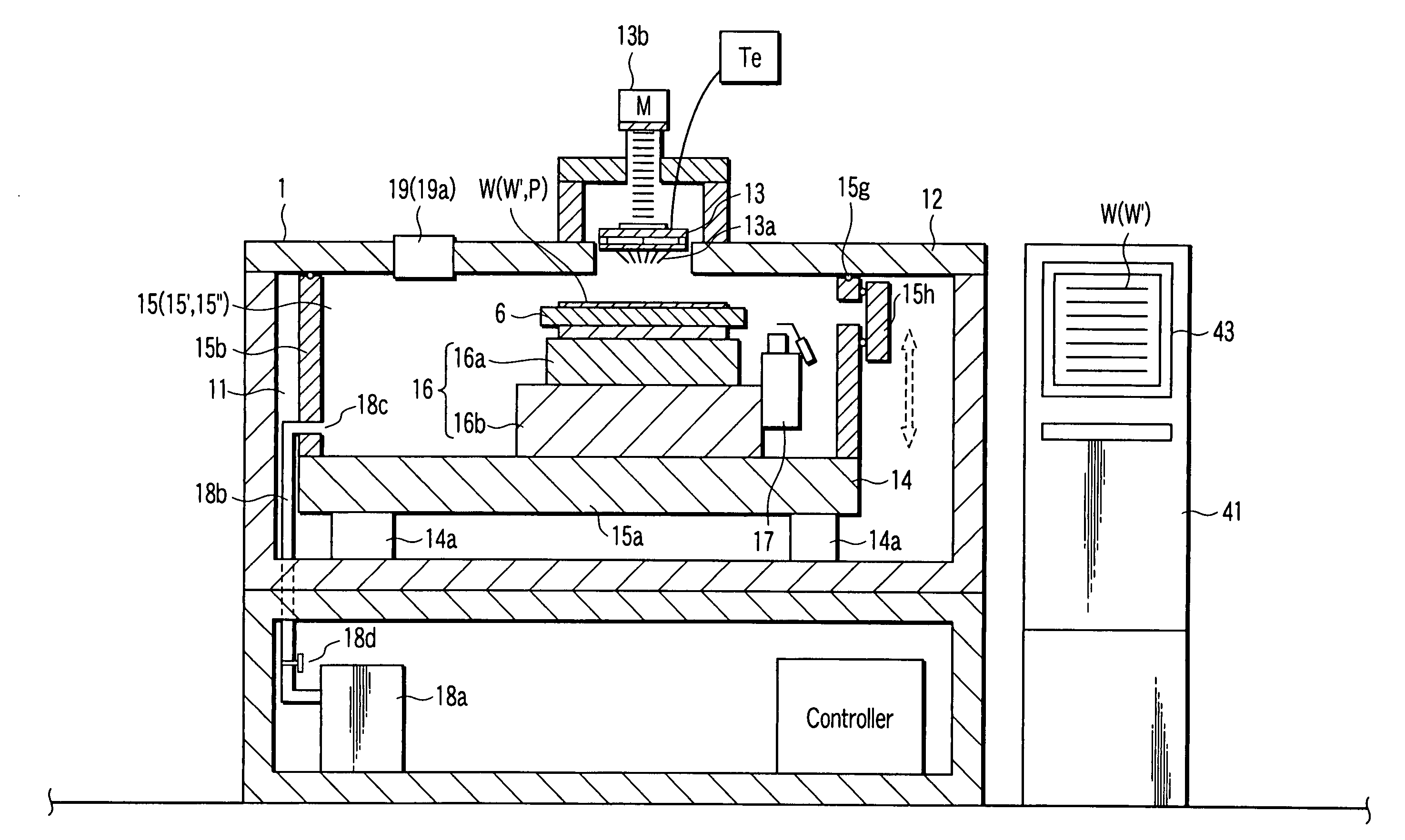
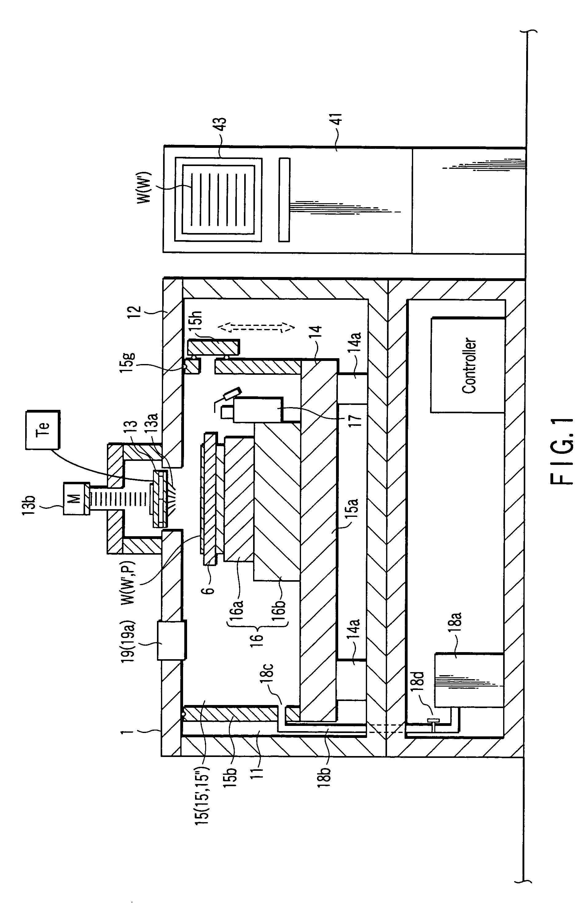
[0087]A vacuum prober according to the present invention will be described with reference to FIG. 1. A vacuum probe 1 system shown in FIG. 1 can have a loader device 41 and prober 1. The loader device 41 stores and transports a wafer W. The prober 1 tests the electrical characteristics of the wafer W moved from the loader device 41. The loader device 41 can include a subchuck. The subchuck prealigns the wafer W with reference to an orientation flat or notch of the wafer W while transporting the wafer W to the vacuum prober 1.
[0088]A stage 14 is arranged in a prober chamber 11 of the vacuum prober 1. A first moving mechanism 14a vertically moves the stage 14 in the Z direction.
[0089]A recessed chamber 15 is formed on the stage 14. A table 6, X-Y moving mechanism 16b, θ rotary mechanism 16a, lower camera 17, exhaust port 18c of a pipe 18b, and valve 18d are arranged in the recessed chamber 15. The wafer W transported from the loader device 41 is to be placed on the table 6. The X-Y mo...
second embodiment
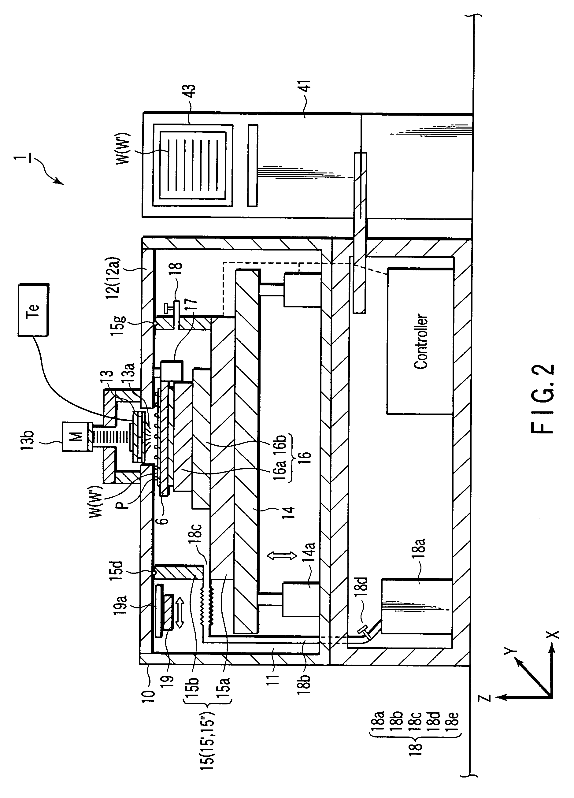
[0103]A vacuum prober 1 according to the present invention will be described with reference to FIG. 2. In the vacuum prober 1, a vacuum chamber 15″, a stage 14 for placing the vacuum chamber 15″ thereon, and mechanisms relating to alignment are different from those of the conventional device described in patent reference 1. Other mechanisms such as a table 6 can be formed in the same manner as in the conventional device.
[0104]The stage 14 is arranged in a prober chamber 11. A first moving mechanism 14a vertically moves the stage 14 in the Z direction.
[0105]A contact holding mechanism 13 and upper camera 19 can be provided to the upper portion of the prober chamber 11. The contact holding mechanism 13 has a plurality of contacts 13a. The upper camera 19 images upward.
[0106]When probes 13a are employed as the contacts 13a, a probe card 13 can be employed as the contact holding mechanism 13 (in the following description, the contacts and the contact holding mechanism will be respective...
third embodiment
[0140]the present invention will be described with reference to FIG. 5.
[0141]A vacuum prober 1 according to the third embodiment has a prober chamber 11. A stage 14 is arranged in the prober chamber 11. A first moving mechanism 14a moves the stage 14 in the X, Y, and Z directions.
[0142]A contact holding mechanism (e.g., a probe card) 13 and upper camera 19 can be provided in the upper portion of the prober chamber 11. The contact holding mechanism 13 has a plurality of contacts 13a. The upper camera 19 images downward. As the contacts 13a, bump-like contacts, needle-like probes, or the like can be employed (the contacts will be referred to as “probes” hereinafter). In the second embodiment, a case in which a probe card 13 having a plurality of probes 13a is employed will be described, but the present invention is not limited to this case. The probe card 13 having the probes 13a is vertically moved in the Z direction by a third moving mechanism 13b.
[0143]The contact holding mechanis...
PUM
 Abstract
Description
Claims
Application Information
 - R&D
- Intellectual Property
- Life Sciences
- Materials
- Tech Scout
- Unparalleled Data Quality
- Higher Quality Content
- 60% Fewer Hallucinations
Browse by: Latest US Patents, China's latest patents, Technical Efficacy Thesaurus, Application Domain, Technology Topic, Popular Technical Reports.
© 2025 PatSnap. All rights reserved.Legal|Privacy policy|Modern Slavery Act Transparency Statement|Sitemap|About US| Contact US: help@patsnap.com