Residual-current circuit breaker and a method for testing the reliability performance of a residual-current circuit breaker

a residual-current circuit and circuit breaker technology, applied in circuit breakers, emergency protective arrangements for limiting excess voltage/current, instruments, etc., can solve problems such as inability to test current permanently, current continues to flow, and the arrangement of an auxiliary switch on the other hand requires additional measures and is not always possible. , to achieve the effect of simple and functional reliability

Inactive Publication Date: 2007-05-22
SIEMENS AG
View PDF11 Cites 9 Cited by
  • Summary
  • Abstract
  • Description
  • Claims
  • Application Information

AI Technical Summary

Benefits of technology

[0007]An embodiment of the invention is based on an object of specifying a fault-current circuit breaker and/or a method f

Problems solved by technology

When two conductors are short-circuited for test purposes, there is a problem in that, in some circumstances, a test current will flow permanently via the test circuit for as long as the test contact is operated.
This problem occurs when connection of the test circuit to the conductors of the conductor network is made on the mains voltage supply side, that is to say upstream of the circuit breaker switching mechanism, so that current continues to flow in the test circ

Method used


Image

  • Residual-current circuit breaker and a method for testing the reliability performance of a residual-current circuit breaker
  • Residual-current circuit breaker and a method for testing the reliability performance of a residual-current circuit breaker
  • Residual-current circuit breaker and a method for testing the reliability performance of a residual-current circuit breaker

Examples


Embodiment Construction

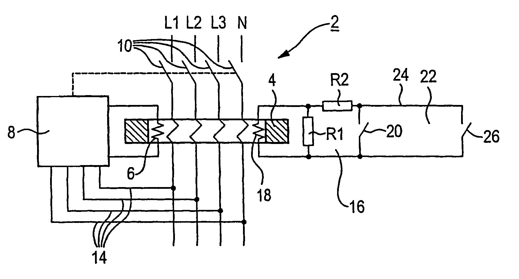
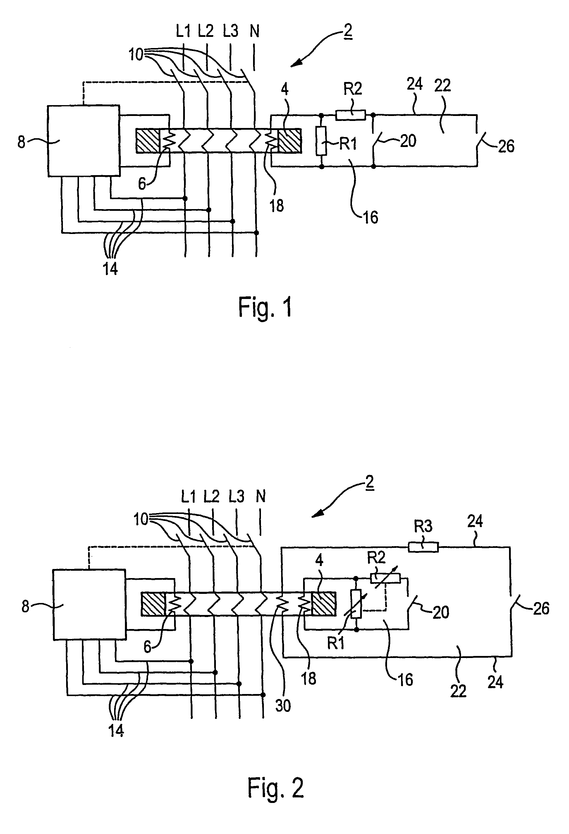
[0034]As shown in FIG. 1, a fault-current circuit breaker 2 has a core-balance current transformer 4, a control winding 6 wound around it, and a functional unit 8. The latter not only has actuation and evaluation electronics for the control winding 6, but also a tripping mechanism. The conductors L1, L2, L3 and the neutral conductor N of a conductor network are passed through the core-balance current transformer 4. Each conductor L1–L3, N has an associated interrupter switch 10, via which the conductors L1–L3, N are disconnected by means of a switching mechanism 12, which is represented by dashed lines, when an unacceptable fault current occurs.

[0035]Supply lines 14 lead from the individual conductors L1–L3, N to the functional unit 8, in order to provide a power supply for the electronics integrated in it. The circuit breaker 2 as shown in FIG. 1 is thus, by definition, in the form of a main-dependent DI circuit breaker.

[0036]In addition to the already described elements, which eve...


PUM


Abstract

A test circuit is provided, which is independent of a power supply and which enables a circuit breaker to be tested in a reliable manner. The test circuit includes a test coil which is devoid of electric potential and is wound around a totalizing current transformer. The test coil is preferably short circuited using a test switch and a connectable load. This simulates the occurrence of a residual current. The selection of an appropriate connectable load allows the sensitivity of the current circuit breaker to be tested in an advantageous manner.

Description

[0001]This application is the national phase under 35 U.S.C. § 371 of PCT International Application No. PCT / EP01 / 04618 which has an International filing date of Apr. 24, 2001, which designated the United States of America, the entire contents of which are hereby incorporated by reference.FIELD OF THE INVENTION[0002]The invention generally relates to a fault-current circuit breaker. In particular, it relates to a differential-current circuit breaker, having a core-balance current transformer and a control winding wound around it. The invention also generally relates to a method for checking the reliability of such a fault-current circuit breaker.BACKGROUND OF THE INVENTION[0003]Fault-current circuit breaker are used in electrical systems, in order to protect personnel against dangerous body currents. When a fault current occurs, the circuit breaker disconnects the conductors of a conductor network. The circuit breaker is used as an autonomous unit, or else as an additional module for...

Claims


Application Information

Patent Timeline
IPC IPC(8): H02H3/16H02H3/33
CPCH02H3/335H02H3/332
Inventor BAUER, BERNHARD
Owner SIEMENS AG
Why Eureka
Try Eureka