Method and device for the optical measurement of state variables and the level in a container for liquefied gases, and device therefor

Active Publication Date: 2010-11-11
MAGNA STEYR FAHRZEUGTECHN
View PDF5 Cites 7 Cited by
  • Summary
  • Abstract
  • Description
  • Claims
  • Application Information

AI Technical Summary

Benefits of technology

[0006]An object of the invention is to provide a method which overcomes the above problems and provides a comprehensive “image” of the state variables in the container as a basis for vehicle operation. In this case “image” is meant in the transcribing sense: states which are associated with individual points in the container and can be connected to form locus curves of identical states. A further object is to provide a device for carrying out the method, which is simple and functionally reliable even in the severe conditions in a motor vehicle.
[0016]Since only the end surface at the inner end of the optical waveguide is in contact with the surrounding medium, the difference, caused by partial reflection, between the light intensities before and after passing through the optical waveguide is greater and can therefore be measured more accurately than with an optical waveguide whose outer surface touches the surrounding medium and which emits limits thereto only by scattering. Furthermore, according to the invention, a measurement is taken only at a defined point. This is the only way in which it is possible to detect not only the phase state but also state variables in the relatively narrow sense, such as mass density and temperature, with good accuracy. The multiplicity of measurement points which are distributed in the area of the container and whose position is known results in a three-dimensional “image” of the state variables, at least along the optical waveguide bundle which is routed or laid in a suitable manner in the area of the container, in which case the word “image” should be understood in the wider sense.
[0019]There are various options for delaying and routing of the strand in the container, routing it such that it passes a plurality of spatial points. To this end, it is advantageous for the strand which forms the bundle to be surrounded by an envelope tube, best of all at a short radial distance, which envelope tube forms a vessel which communicates with the content of the container. The envelope tube is therefore used not only to guide and support the strand, but in fact damps rapid changes in the liquid level, which occur during use in a vehicle.
[0020]In one preferred embodiment, the envelope tube is curved, and the strand which forms the bundle is flexible, and is preferably spatially curved and is attached to the inner wall of the container. Measurement points can thus be arranged at all the major points, using a single envelope tube and a single strand guided therein. The envelope tube is permanently installed at the same time that the container is constructed, and the flexible strand can be inserted into the envelope tube later, from the outside. This means that the strand can also easily be replaced. If the envelope is in the form of a helical line, it can be attached to the inner wall of the container (for example by welding) over its entire length, and can be provided with holes distributed over the length. The former provides protection against sensitivity to oscillations, and the holes ensure communication between the container content and the space between the strand and the envelope tube, for all filling levels.
[0021]A single image sensor such as the type normally used in video cameras is advantageously used for measurement of the amount of light returning from the optical waveguides via the common beam splitter. One cheap mass-produced item is therefore used instead of a multiplicity of individual sensors. The planar arrangement of a×b pixels is utilized particularly well if each optical conductor has an associated field of a plurality of pixels, of 4 to 25 pixels, preferably 9. The light which is reflected in the respective optical waveguide is thus imaged onto a field such as this with a side length of 3 to 5 pixels. This makes it possible to compensate for position tolerances and the failure of one pixel.

Problems solved by technology

Conventional level measurement systems have either not satisfied the requirements or have been found to be much too expensive and also unreliable.
Electrical measurement methods (capacitive, inductive) require the introduction of electrical lines into the (double-walled) container, which results in heat bridges and a risk of explosion, and, furthermore, they are susceptible to defects and are sensitive to disturbances.
Scattering losses occur in consequence as a function of the refractive index of the container content touching the sensor surface, and these losses increase in proportion to the sensor area and thus to the container content.
However, because of the poor dependency of the liquid level on the scattering losses and because of the cumulative evaluation of all the scattering losses for the determination of the position of the liquid level, this is not sufficiently accurate.

Method used


Image

  • Method and device for the optical measurement of state variables and the level in a container for liquefied gases, and device therefor
  • Method and device for the optical measurement of state variables and the level in a container for liquefied gases, and device therefor
  • Method and device for the optical measurement of state variables and the level in a container for liquefied gases, and device therefor

Examples


Embodiment Construction

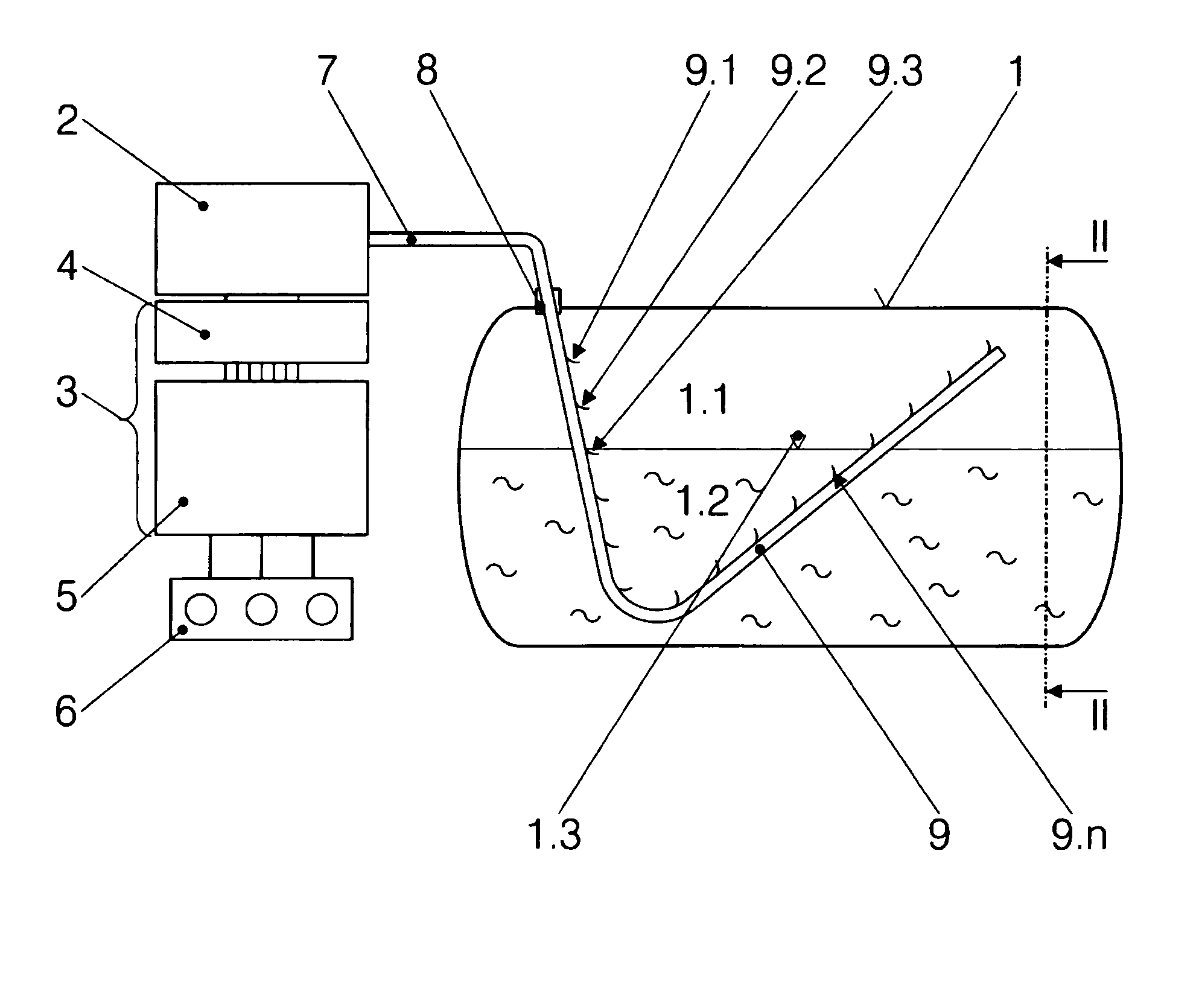
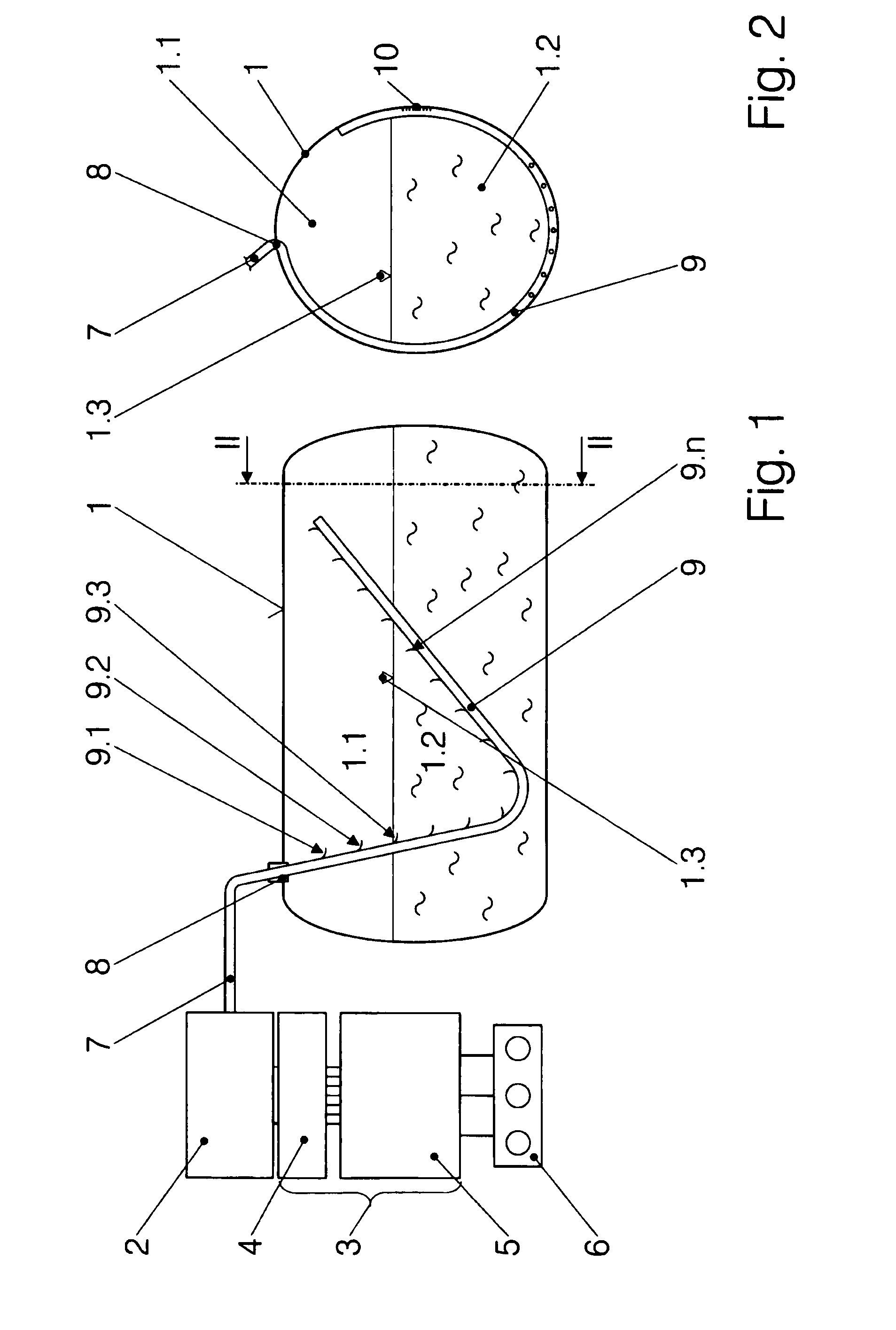
[0029]FIG. 1 indicates a container for liquefied cryogenic gases only by means of its wall 1. Physical containers are generally double-walled with a highly insulating space between them. The cryogenic gas in its interior forms a gaseous phase 1.1 and a liquid phase 1.2, which is separated from the gaseous phase 1.1 by a liquid level 1.3. A device which comprises a lighting unit 2 and an evaluation unit 3, outside the container, is provided in order to determine state variables of the container content. The evaluation unit 3 comprises an image sensor 4, a computer 5 and an indication of the determined state variables or amount contained 6. Furthermore, the device comprises an optical waveguide unit, which originates from the lighting unit 2 and comprises an outer part 7 and an inner optical waveguide unit, the inner part 9, which is passed through a bushing 8 into the interior of the container 1. As described in more detail further below, the optical waveguide unit 7, 9 contains a nu...


PUM


Abstract

A method and a device for optically determining state variables inside a container (1) for liquefied gases. In the method and device, light emitted by an illumination unit (2) travels within an optical waveguide (7, 9) to a contact point (33) with the content of the container (1) and is partially reflected there, the intensity of the reflected light is measured by an image sensor (4), and a state variable is determined from the intensity. In order to create a comprehensive “image” of the state variables in the container and of the container content, several optical waveguides (29, 29′) are guided to contact points (33) which are distributed within the container (1) and form measurement points (9.1, 9.2, 9.3, . . . , 9.n). Locally assigned state variables (refractive index, density, temperature, etc.) of the container content are determined from the measured values obtained at the measurement points (9.1, 9.2, 9.3, . . . , 9.n) and are evaluated along with the spatial coordinates of the measurement points (9.1, 9.2, 9.3, . . . , 9.n) in the container (1).

Description

BACKGROUND OF THE INVENTION[0001]The invention relates to a method for the optical determination of state variables in the interior of a container for liquidified gases, where light which is emitted from a lighting unit is carried in an optical waveguide to a contact point with the content of the container, where it is partially reflected and the light intensity of the reflected light is measured, and a state variable is determined from this and from the light intensity of the light emerging from the light source.[0002]The container is intended to be a container for low-boiling-point gases—in particular hydrogen—which is carried by a motor vehicle, with the gases being used as fuel. Liquefied low-boiling-point gases are stored in conditions (pressure and temperature) in which the state variables of the liquid phase and of the gaseous phase differ only slightly. Furthermore, the physical and thermal characteristics, in particular of hydrogen, and the heat which is invariably introduc...

Claims


Application Information

Patent Timeline
IPC IPC(8): G01F23/292
CPCG01D5/35303G01F23/292G01N2201/0846G01N21/4133G01N21/00G01D5/35358
Inventor KRAMMER, GERT
Owner MAGNA STEYR FAHRZEUGTECHN
Why Eureka
Try Eureka