
Fish slaughter device and trigger device configured for same

a trigger device and fish technology, applied in slaughtering devices, butchering, food science, etc., can solve the problems of inability to adjust the size-dependent adjustment inability to adjust the size of the fish head abutment element, and impairment of the fish throughput rate, etc., to achieve optimally reduce the mass of the trigger element, functionally reliable, and simple

Active Publication Date: 2020-06-16
NORDISCHER MASCHINENBAU RUD BAADER GMBH CO KG
View PDF24 Cites 0 Cited by
  • Summary
  • Abstract
  • Description
  • Claims
  • Application Information

AI Technical Summary

Benefits of technology

The invention is a trigger device and fish slaughter device that improves processing efficiency and complies with animal welfare regulations. The trigger device uses a special mechanism to determine the position of the fish head based on the size and trigger positions of the fish head abutment element. The device also has a simple and adjustable mechanism for adjusting the position of the fish head abutment element for different fish sizes. The trigger device is designed to be functionally reliable and sensitive to small fish impacts, and the overall operation is efficient and effective. The clamping device helps in easy and refined adjustment for different fish species. The trigger device allows for easy and precise triggering without high costs or complexity. Overall, the invention simplifies fish processing and improves the fish throughput rate while maintaining compliance with animal welfare regulations.

Problems solved by technology

Although the use of a simple pressure piston cylinder, whose actuator element can only be brought into limit positions, simplifies the control system in respect of higher throughput speeds, size-dependent adjustment of the fish head abutment element remains limited, particularly also with regard to processing that is animal welfare-compliant.
This results in a susceptibility to malfunctioning and impairment of the fish throughput rate.

Method used


Image

  • Fish slaughter device and trigger device configured for same
  • Fish slaughter device and trigger device configured for same
  • Fish slaughter device and trigger device configured for same

Examples


Embodiment Construction

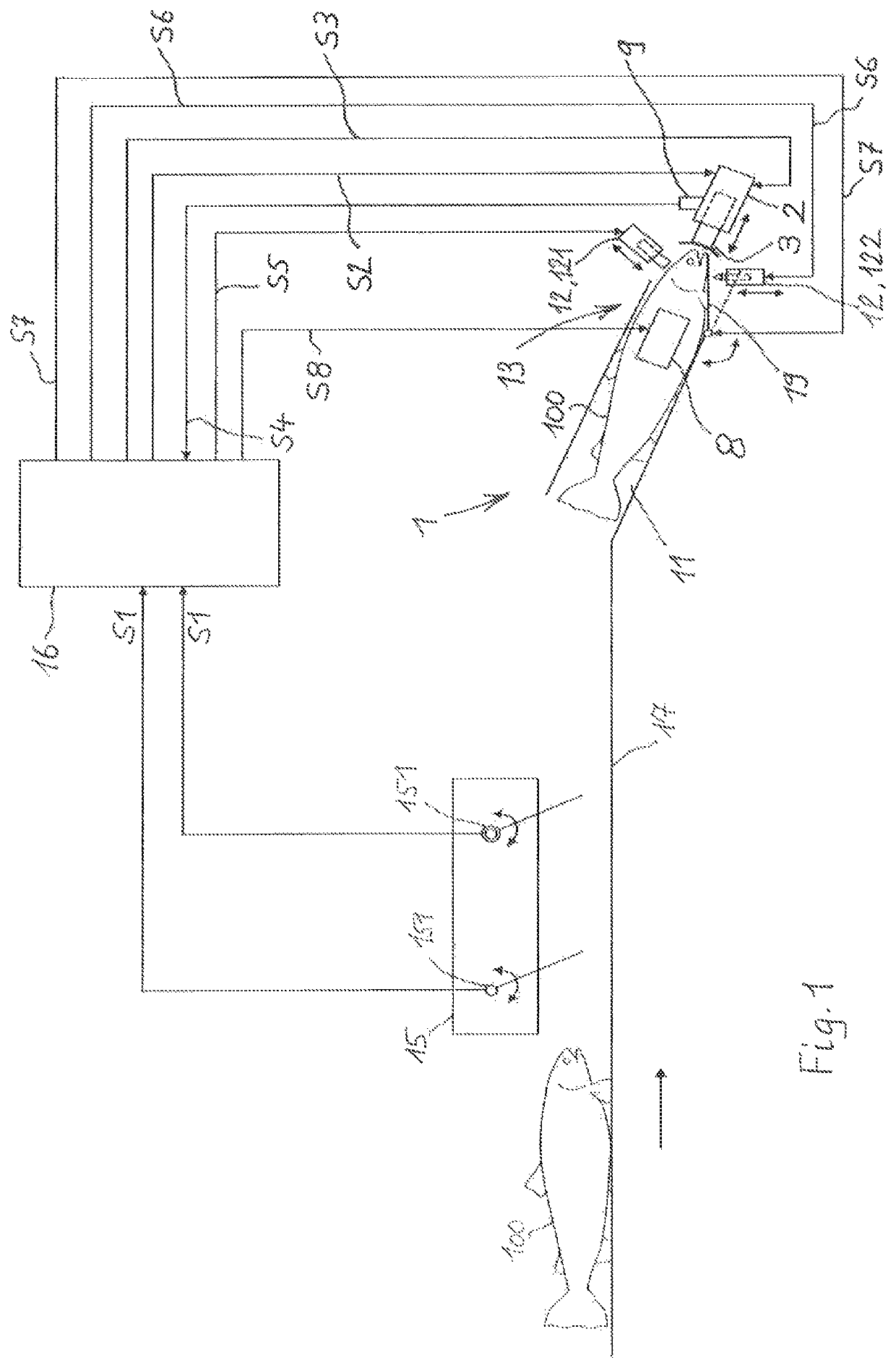
[0032]FIG. 1 shows a schematic representation of a fish slaughter device 1 according to the invention in conjunction with associated operating devices, namely a fish feed-in device 17, a fish-size determining device 15, a device controller 16 and a controllable trigger device 2 according to the invention.

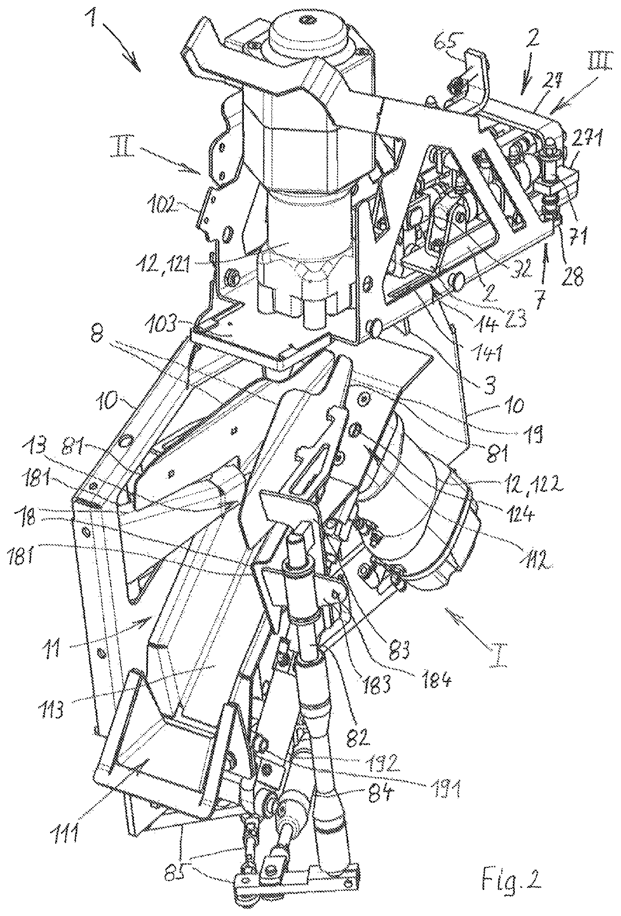
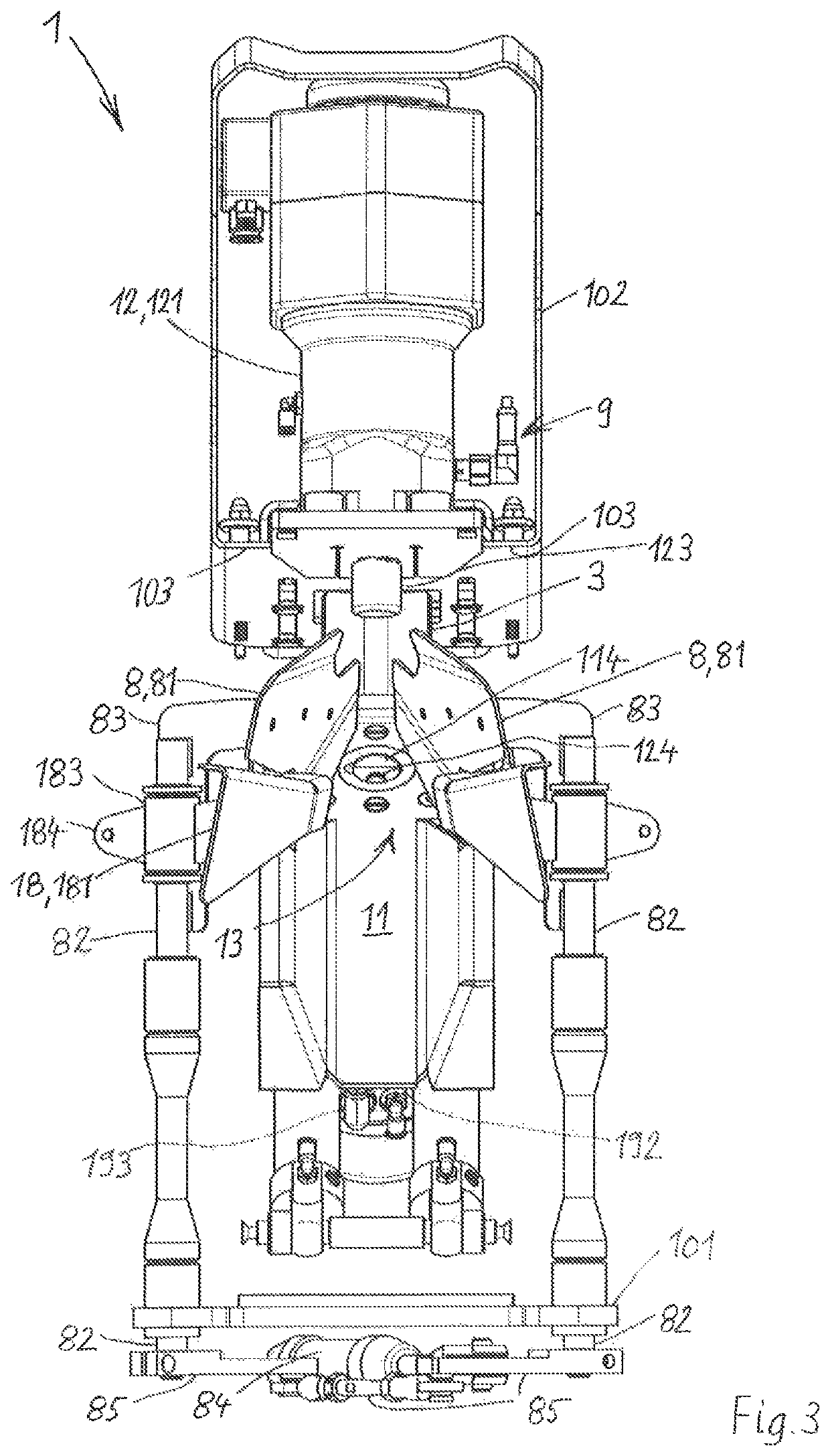
[0033]The fish slaughter device 1 comprises a fish receiving space 11, a fish positioning device 13, a trigger sensor device 9, the controllable trigger device 2 and controllable fish slaughter tools 12. A first fish slaughter tool 12 is a stunning tool 121, which acts mechanically on the skull in the head region of the fish 100. A second fish slaughter tool 12 is a bleeding tool 122, which is assigned to the fish underside in the region between head and gills for severing the main artery.

[0034]The fish positioning device 13 has a fish head abutment element 3 and a delivery mechanism formed by a pivotable floor flap 19 for releasing and delivering a processed fish 100. The fish posi...


PUM


Abstract

Fish slaughter device includes fish positioning device with fish head abutment, against which the fish head abuts temporary stop position by controllable fish slaughter tool. Fish head abutment element is a trigger releasable by a trigger sensor of a controllable trigger controllable to move the fish head abutment into different trigger positions. device includes a first control actuator with a first actuator, a coupling device, connecting the fish head abutment to the first actuator for adjusting movement into the trigger positions, and an additional second control actuator with a second actuator controllably placeable in at least two fixed trigger adjustment positions. The two actuators are coupled so an adjusting movement of the first actuator is stopped by a coupling impact against the second actuator in a fixed trigger adjustment positions, which brings about an associated trigger position of the fish head abutment.

Description

CROSS-REFERENCE TO RELATED APPLICATIONS[0001]The instant application is a US National stage of PCT International Application No. PCT / EP2016 / 066325 filed Jul. 8, 2016.BACKGROUND OF THE INVENTION1. Field of the Invention[0002]The invention relates to a fish slaughter device, comprising a fish receiving space, which can be charged with fish to be slaughtered in the head-first position through a receiving space entry, and a fish positioning device, configured for controllably holding and positioning a fish in the fish receiving space in a temporary stop position of said fish, which is associated with at least one controllable fish slaughter tool for slaughtering the fish, and also configured for controllably releasing the slaughtered fish; the fish positioning device comprises a fish head abutment element, against which the fish head of the fish abuts in the temporary stop position, which in addition forms a trigger element for controlling the at least one controllable fish slaughter to...

Claims


Application Information

Patent Timeline
Patent Type & Authority Patents(United States)
IPC IPC(8): A22B3/00A22B3/08A22B7/00
CPCA22B3/08A22B7/001A22B3/083
Inventor RUSKO, TORSTENRUNGE, DIRKPAGELS, MIRKO
Owner NORDISCHER MASCHINENBAU RUD BAADER GMBH CO KG
Learn More