Shredder with cage relief

a cage relief and shredder technology, applied in the direction of cocoa, sorting, solid separation, etc., can solve the problems of backlog, jamming of material in the mill, damage to the mill,

Inactive Publication Date: 2007-05-29
WILLIAMS JR ROBERT M
View PDF8 Cites 28 Cited by
  • Summary
  • Abstract
  • Description
  • Claims
  • Application Information

AI Technical Summary

Benefits of technology

[0008]In the event hard to grind tramp material is fed into the processing system, the force imposed on the material by the rotor may cause damage to the mill. Simultaneously, continued feed of additional material may result in a backlog and jamming of material in the mill. Preventing the occurrence of mill damage and material jam is of u...

Problems solved by technology

In the event hard to grind tramp material is fed into the processing system, the force imposed on the material by the rotor may ca...

Method used


Image

  • Shredder with cage relief
  • Shredder with cage relief
  • Shredder with cage relief

Examples


first embodiment

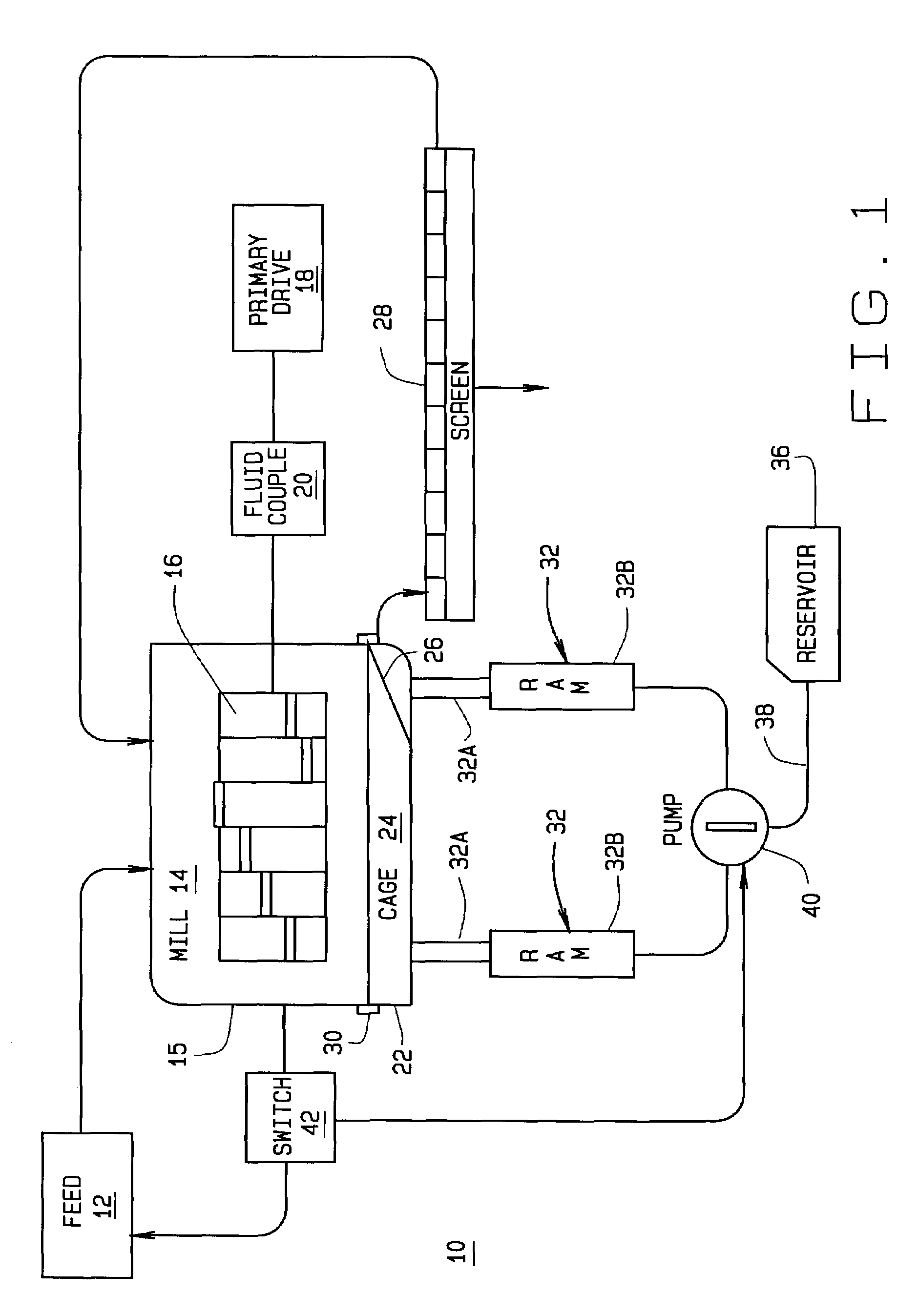
[0025]In a first embodiment, show in FIG. 1, the arms hydraulic rams 32 are in the first operational position when each ram arm 32A is extended, exerting a pushing force on the pivoting cage 24 to maintain it in the closed and operational position. To maintain the first operational position, the hydraulic pump 40 provides hydraulic fluid from the reservoir 36 to each fluid cylinder 32B, through the hydraulic circuit 38. Upon receiving a signal from the speed sensor switch 42 or control system to release and open the pivoting cage 24, the hydraulic pump 40 is reversed, drawing fluid from each fluid cylinder 32B and returning it to the reservoir 36. Alternatively, hydraulic pump 40 is disengaged, and a fluid return bypass is opened, permitting fluid to drain from each fluid cylinder 32B back to the reservoir 36. As fluid is withdrawn or drained from each fluid cylinder 32B, each ram arm 32A retracts, drawing the pivoting cage 24 away from the rotor 16, and into an open position for di...

second embodiment

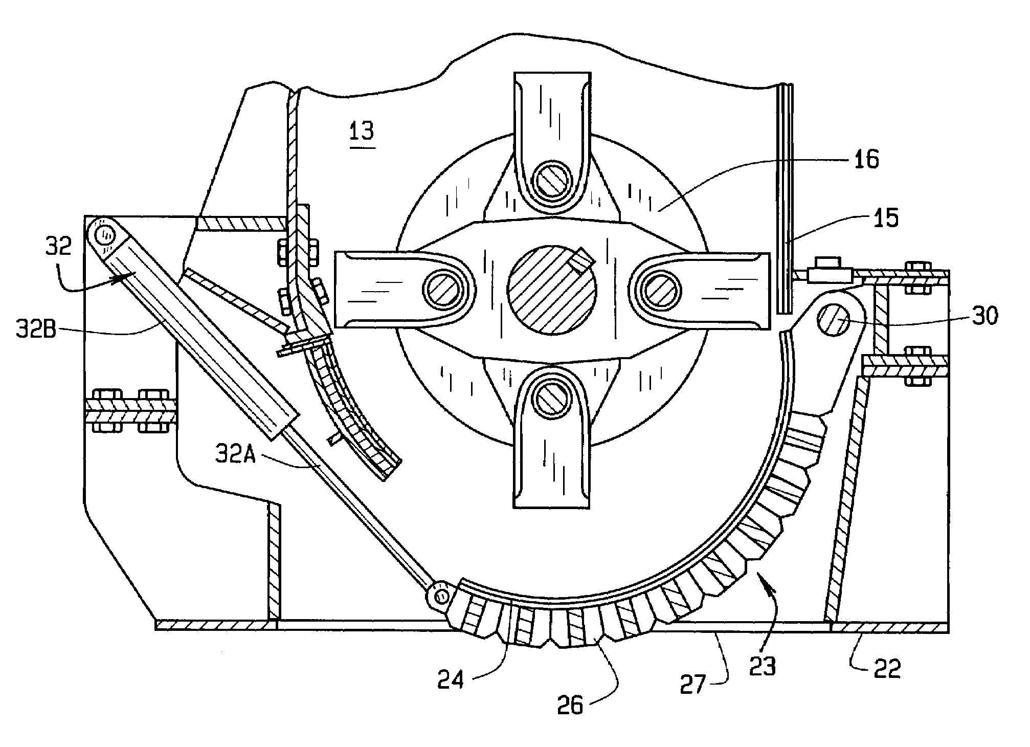
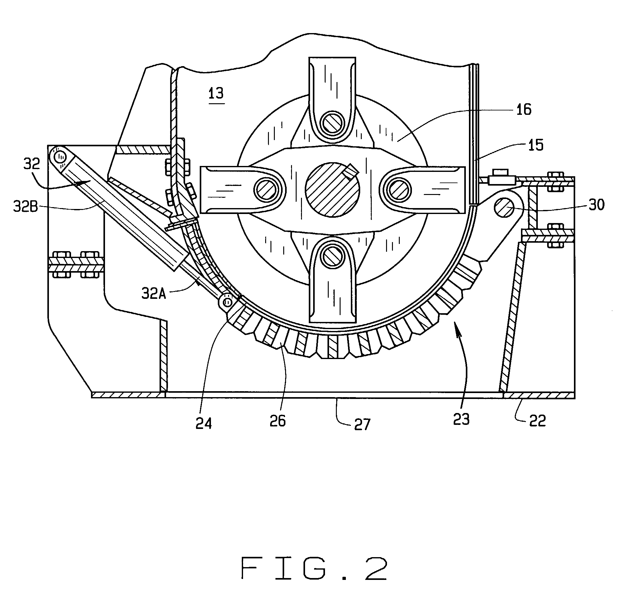
[0026]In a second embodiment, show in FIGS. 2 and 3, the arms hydraulic rams 32 are in the first operational position when each ram arm 32A is retracted, exerting a draw force on the pivoting cage 24 to maintain it in the closed and operational position. To maintain the first operational position, the hydraulic pump 40 draws hydraulic fluid from each fluid cylinder 32B, through the hydraulic circuit 38, and stores it in the reservoir 36. Upon receiving a signal from the speed sensor switch 42 or control system to release and open the pivoting cage 24, the hydraulic pump 40 is reversed, drawing fluid from the reservoir 32 and supplying hydraulic fluid under pressure to each fluid cylinder 32B. As the hydraulic fluid is pumped into each fluid cylinder 32B, the associated ram arms 32A extend, moving the pivoting cage 24 to an open configuration shown in FIG. 3 for the discharge of the trapped or jammed tramp material.

[0027]Those of ordinary skill in the art will recognize that the hydr...


PUM


Abstract

A materials processing system adapted for the reduction of metallic materials including a material feed portion configured to convey materials to a mill portion comprising a motor driven rotor in close running fit with a cage mounted grate through which reduced material is discharged onto a conveyer. The cage is biased to a closed operating position by one or more hydraulic rams. A control system receives signals from a speed sensor operatively coupled to the rotor, and is configured to regulate the hydraulic rams, thereby controlling the opening and closing of the cage in response to rotation of the rotor. The control system is further configured to regulate the operation of the materials feed portion to suspend material feed during opening of the cage, permitting trapped or jammed material to be expelled from the mill portion.

Description

CROSS-REFERENCE TO RELATED APPLICATIONS[0001]Not Applicable.STATEMENT REGARDING FEDERALLY SPONSORED RESEARCH[0002]Not Applicable.BACKGROUND OF THE INVENTION[0003]The present invention is generally related to apparatus for grinding and granulating various types of waste material which may contain hard to grind stray materials, and in particular, to an adaptation to a materials processing system which is adapted to protect the grinding and driving components of the system from damage when such hard to grind stray materials becomes trapped or jammed within the grinding components.[0004]In conventional apparatus configured for the processing of material by grinding, shredding, or crushing, there is a constant problem associated with the intake of material which is either to large or to hard for the apparatus to effectively reduce. Such material, commonly referred to as “tramp material”, can become trapped or jammed within the grinding, shredding, or crushing components, resulting in sev...

Claims


Application Information

Patent Timeline
IPC IPC(8): B02C13/284B02C13/286B02C13/00
CPCB02C13/284B02C13/286B02C13/31B02C18/2216B02C18/24B02C2018/164
Inventor WILLIAMS, JR., ROBERT M.
Owner WILLIAMS JR ROBERT M
Why Eureka
Try Eureka