Bulk bag discharging system assembly

a technology of discharging system and bag, which is applied in the direction of flexible bulk container emptying system, liquid handling, packaging goods type, etc., can solve the problems of no convenient way to seal the bag in a dust-free manner, extreme difficulty in known bulk bag system,

Active Publication Date: 2007-05-29
MATERIAL TRANSFER & STORAGE
View PDF26 Cites 29 Cited by
  • Summary
  • Abstract
  • Description
  • Claims
  • Application Information

AI Technical Summary

Problems solved by technology

This is extremely difficult in known bulk bag systems employing a dust free chamber around the dispensing spout because the dispensing spout is normally contained within a square chamber.
As a result, there is no convenient way to seal the bag in a dust free manner because, before the bag is untied to release the contents, the loose bag material must be fitted around the dispensing spout, which is difficult if not impossible, for an operator when the only access point is a single door on one side of the chamber.
The single door does not allow the operator to easily reach around the entire circumference of the spout and fit the loose bag material over the spout.
Additionally, prior bulk bag dispensing systems have used V-shaped impactors that run off one pneumatic cylinder and pinch together to squeeze the sides of the bulk bag, thereby preventing the formation of bridging / rat-holing, which is a condition whereby a material arches or bridges across a dispensing hole, resulting in sporadic flow or a complete cessation of flow.
Unfortunately, this design only allows the operator to stop the flow of material by closing the iris shut off valve when the material is flowing out of the bag.
There simply is not enough strength in the prior art iris designs to close the container when the material itself is preventing the iris from closing.

Method used


Image

  • Bulk bag discharging system assembly
  • Bulk bag discharging system assembly
  • Bulk bag discharging system assembly

Examples


Embodiment Construction

)

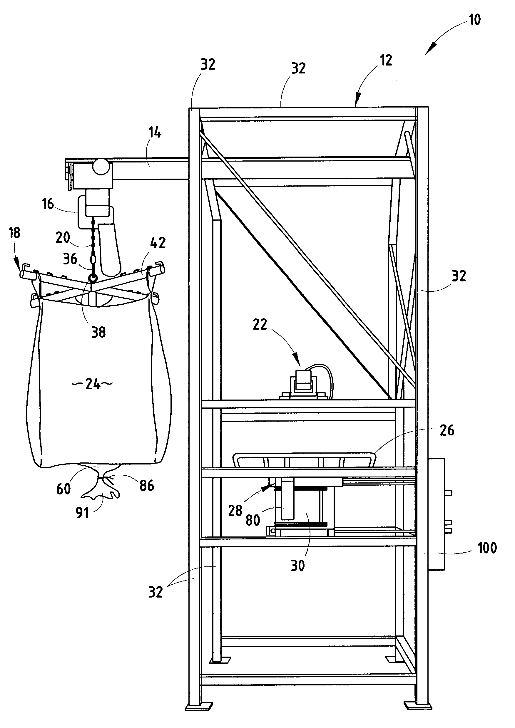
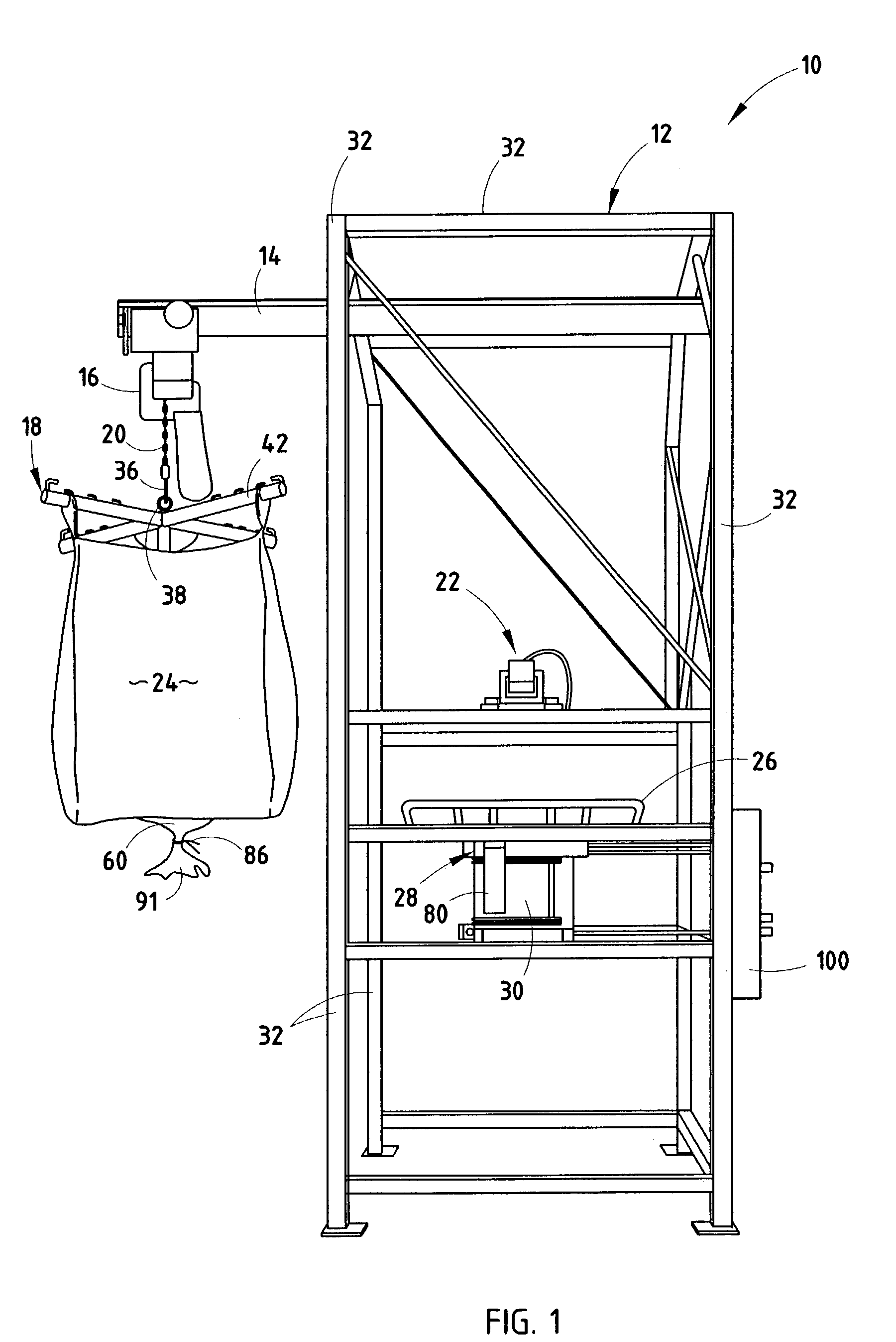
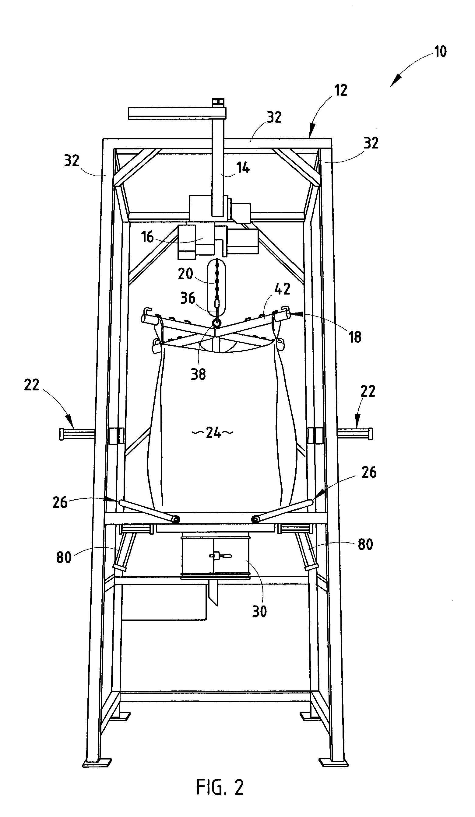
[0022]The discharge assembly 10 of the present invention typically includes a main frame assembly 12 that includes a hoist support 14 engaged to the main frame assembly 12 and a hoist 16 moveably engaged with the hoist support 14; a material container transport assembly 18 engaged to the hoist 16, typically by a heavy-duty chain 20; at least two independently movable material container impactors 22 adjustably engaged to the main frame assembly to accommodate different sized soft-sided material containers (bags) 24; at least two independently movable material container massaging frames 26 engaged to the main frame assembly 12; a discharge receiving gate 28; and a spout access chamber 30.

[0023]The main frame assembly 12 typically utilizes about three inch to about four inch diameter square tubing having about ¼ inch to about ⅝ inch thick walls about the perimeter of the main frame assembly 12. These perimeter pieces 32 are typically continuously welded with one another to provide add...


PUM


Abstract

In one embodiment of the present invention, a material container discharge assembly includes: a main frame assembly; material container impactors engaged to the main frame assembly; a discharge receiving gate having a material container receiving aperture and first, second, and third movable plates, where the first and third plates are movable between an open and closed position and further define a second plate receiving area for receiving the opposed second plate when the second plate and the first and third plates are in the closed position; and a substantially circular access chamber spaced below the material container receiving aperture that includes at least two access doors on substantially opposite sides of the chamber that operate to substantially air tight seal when closed and a sealing system having a sealing device movable between a disengaged position and an engaged position, where the engaged position operates to seal the container in position.

Description

CROSS-REFERENCE TO RELATED APPLICATION[0001]This application claims the benefit of U.S. Provisional Application No. 60 / 378,298, filed on May 6, 2002, the disclosure of which is hereby incorporated by reference in its entirety.BACKGROUND OF THE INVENTION[0002]Bulk bag discharging systems have been used to transfer materials, usually raw materials, from one container into another without contaminating the materials. Generally, bulk bag discharging systems lift a material-containing bag into a dispensing position. Once the bag is in position, an operator must somehow stretch the outlet portion of the bag material that is below a tie off point around a dispensing spout. This is extremely difficult in known bulk bag systems employing a dust free chamber around the dispensing spout because the dispensing spout is normally contained within a square chamber. When a dust free chamber is used, they only employ a single door on one side. As a result, there is no convenient way to seal the bag ...

Claims


Application Information

Patent Timeline
Patent Type & Authority Patents(United States)
IPC IPC(8): B65B21/02B65B43/00B65G65/04B66C1/02B65B69/00B66C1/22B66C19/00
CPCB65B69/0091B66C1/226B66C19/00
Inventor NYHOF, SCOTT L.
Owner MATERIAL TRANSFER & STORAGE
Why Eureka
Try Eureka