
Exerciser with multiple bungee cord resistance and enhanced bench movements

Inactive Publication Date: 2007-05-29
STAMINA PRODS
View PDF8 Cites 30 Cited by
  • Summary
  • Abstract
  • Description
  • Claims
  • Application Information

AI Technical Summary

Benefits of technology

[0003]Recent years have seen an increasing awareness of the benefits of physical exercise and widespread use of exercisers. The therapeutic value of progressive resistance exercises has long been recognized. Exercising muscles against progressively increasing resistance not only results in added strength and endurance in the muscles, but also in a more efficient functioning of the cardiovascular and respiratory systems.

Problems solved by technology

However, varying the resistance by using elastomeric resistance as taught by Piaget et al. involves adding or subtracting individual resistance cords to the apparatus, which can be both burdensome and time consuming.
Further, since the resistance cords are typically separate units, they can be lost or misplaced, increasing costs for replacement, and frequently are strewn about the apparatus in a manner to create substantial tripping hazards.
Even though the exercise machine is relatively versatile, it includes numerous pivotally movable components, which can be relatively bulky and can require many steps to maneuver the exercise machine into various positions for effecting the different modes of exercise.
These extra steps require extra time to move the exercise machine between different positions and can significantly lengthen the workout.
Other exercisers, especially those configured to provide multiple exercises or a bench which may be maneuvered between various positions may be cumbersome to transport and may take up a large area.
The exercise machines taught by Piaget et al. and Whitcomb may also be moved into a storage position, but both exercise machines require a relatively complex series of movements and adjustments before being moved into the storage positions thereof.

Method used


Image

  • Exerciser with multiple bungee cord resistance and enhanced bench movements
  • Exerciser with multiple bungee cord resistance and enhanced bench movements
  • Exerciser with multiple bungee cord resistance and enhanced bench movements

Examples


Embodiment Construction

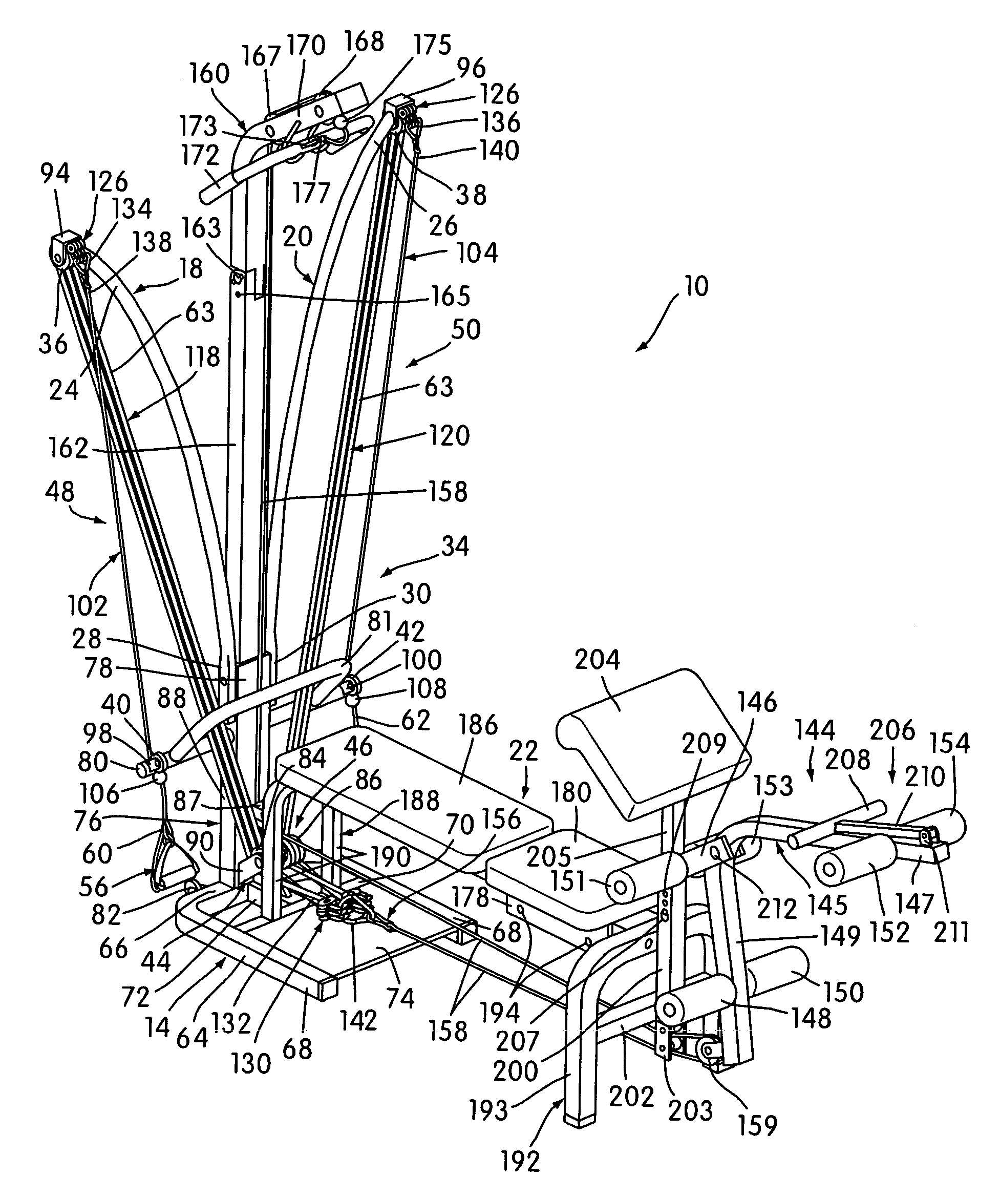
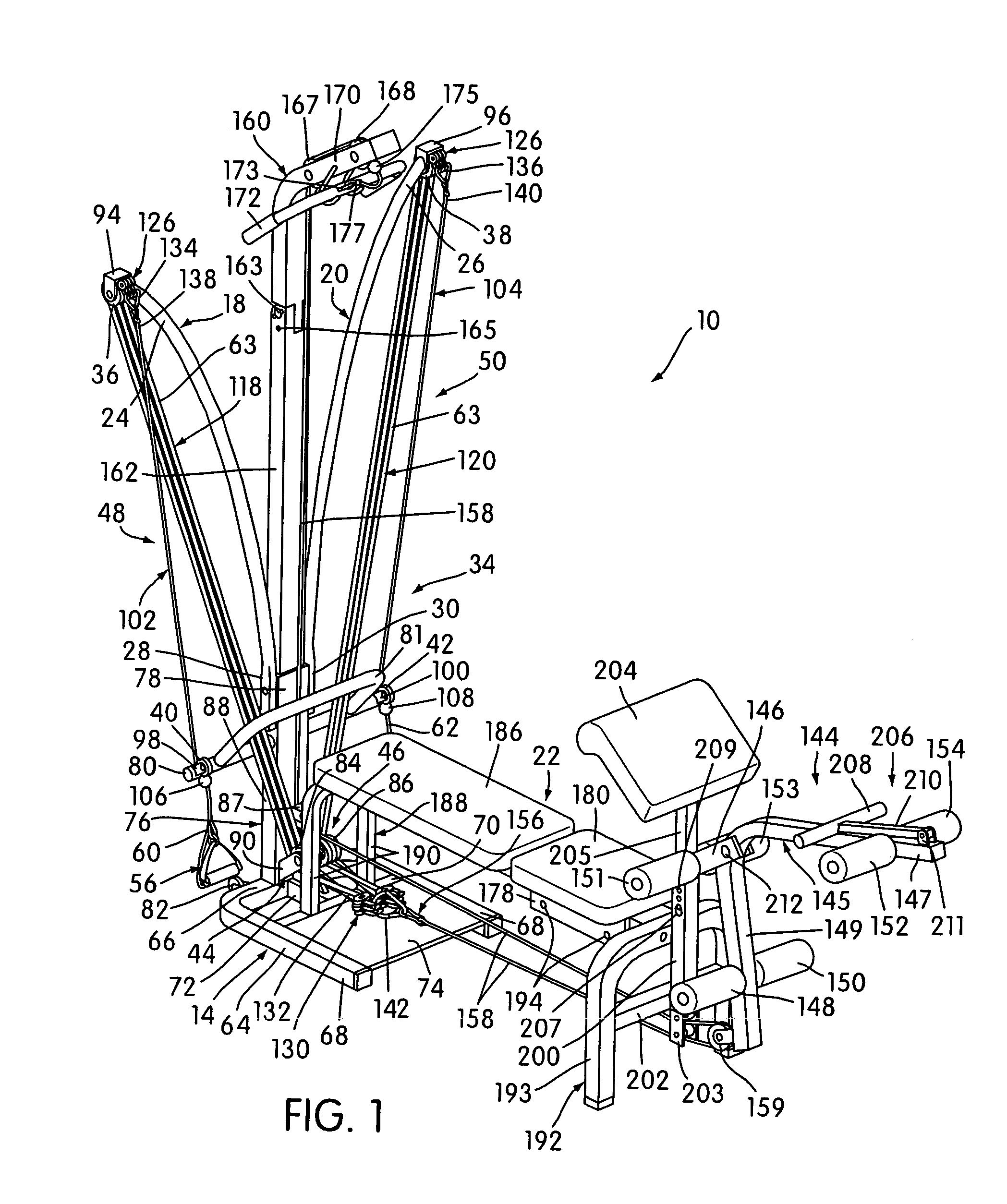
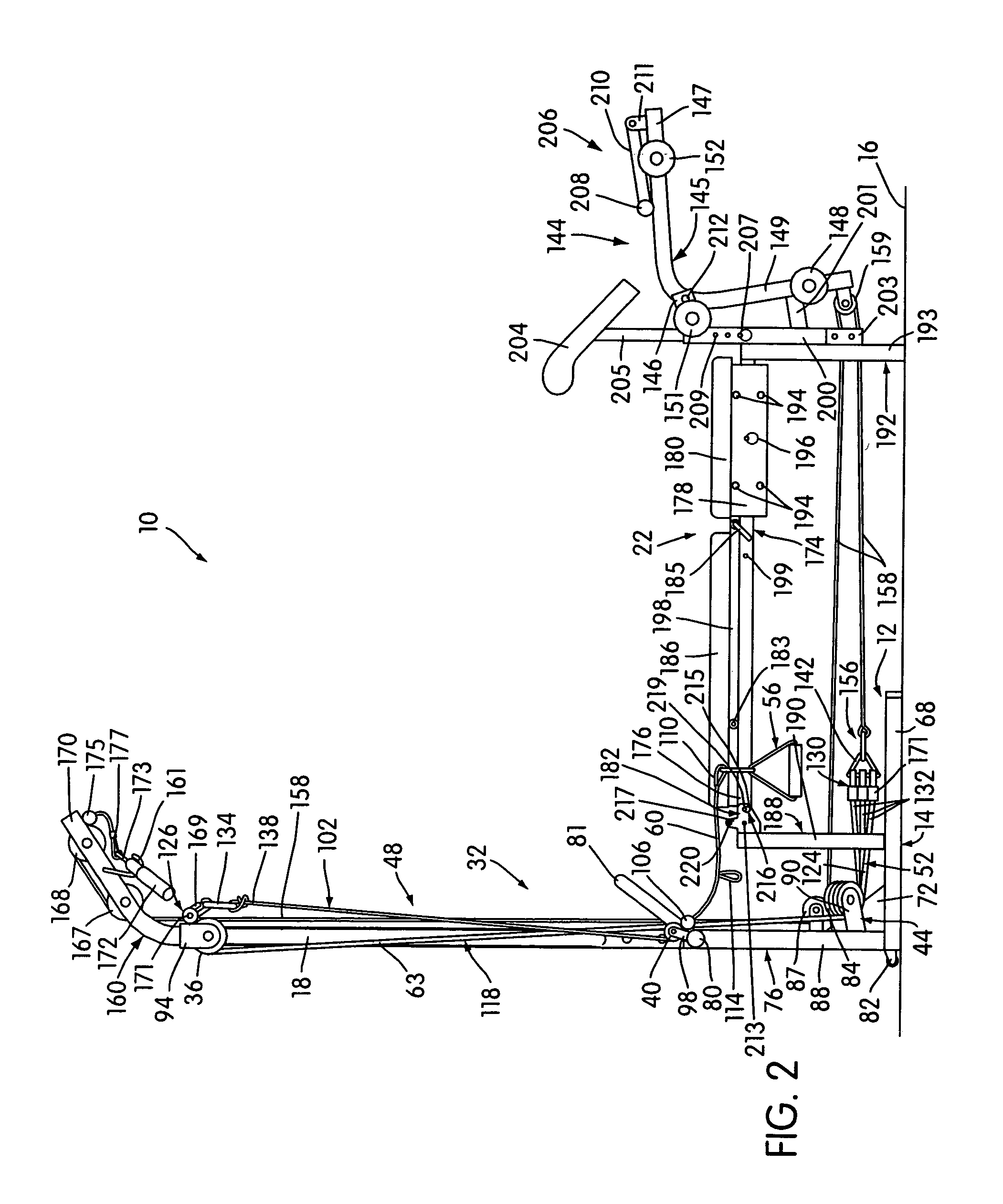
[0059]Referring now more particularly to the drawings, FIGS. 1–3 illustrate an exerciser, generally indicated at 10, embodying the principles of the present invention. The exerciser 10 comprises a frame assembly, generally indicated at 12, having bungee cords 63 mounted thereto to provide resilient resistance to first and second moving assemblies, generally indicated at 32, 34, respectively, a leg-engaging unit, generally indicated at 144, and a hand grip bar assembly, generally indicated at 160. The exerciser 10 further comprises a user support assembly, generally indicated at 22, movable between an inner and outer position thereof by seat back mounting structure.

[0060]The frame assembly 12 includes a lower frame portion, generally indicated at 14, constructed and arranged to be stablely supported in an operative position on a horizontal surface 16 and the user support assembly 22 is operatively connected with the lower frame portion 14 to support a user thereon.

[0061]First and sec...


PUM


Abstract

An exerciser includes a frame assembly including a lower frame portion constructed and arranged to be stably supported in an operative position on a horizontal surface and rigid upright frame structure defining laterally spaced left and right free end portions. A user support assembly is operatively connected with the lower frame portion and is constructed and arranged to support a user thereon. Left and right moving assemblies are disposed in normal inoperative positions with respect to the user support assembly constructed and arranged to be manually engaged and individually manually moved away from the normal inoperative position thereof into a desired extended position by a user supported on the user support assembly.

Description

CROSS-REFERENCE TO RELATED APPLICATION[0001]This application claims the benefit of U.S. patent application Ser. No. 09 / 738,317, entitled “EXERCISER WITH MULTIPLE BUNGEE CORD RESISTANCE AND ENHANCED BENCH MOVEMENTS,” McBride, and filed Dec. 18, 2000, now U.S. Pat. No. 6,595,905, the contents of which are incorporated herein by reference in their entirety.FIELD OF THE INVENTION[0002]This invention relates generally to exercisers and more specifically to exercisers with multiple resistance and bench movements that enable a user to perform various different exercises.BACKGROUND AND SUMMARY OF THE INVENTION[0003]Recent years have seen an increasing awareness of the benefits of physical exercise and widespread use of exercisers. The therapeutic value of progressive resistance exercises has long been recognized. Exercising muscles against progressively increasing resistance not only results in added strength and endurance in the muscles, but also in a more efficient functioning of the card...

Claims


Application Information

Patent Timeline
IPC IPC(8): A63B21/00A63B21/04A63B21/055A63B23/035
CPCA63B21/04A63B21/0552A63B21/151A63B21/154A63B23/035A63B21/1461A63B21/1484A63B21/1492A63B23/03525A63B23/03533A63B23/03566A63B21/00065A63B21/0428A63B21/0557A63B2071/025A63B2208/0233A63B2208/0238A63B21/4031A63B21/4043A63B21/4047
Inventor MCBRIDE, ROBERT W.
Owner STAMINA PRODS
Learn More