Fault monitoring in a distributed antenna system

a distributed antenna and fault monitoring technology, applied in antennas, transmission, modulation, etc., can solve the problems of significant likelihood that one or more antennas or cables may be disconnected or severed, and the loss of service in a section of the facility

Inactive Publication Date: 2007-05-29
P G ELECTRONICS
View PDF9 Cites 262 Cited by
  • Summary
  • Abstract
  • Description
  • Claims
  • Application Information

AI Technical Summary

Problems solved by technology

Many facilities present problems for wireless RF communication signals and require that an in-facility signal distribution system be employed to provide adequate wireless reception and coverage within the facility.
However, experience has shown that the regular maintenance that occurs in many large buildings leads to a significant likelihood that one or more of the antennas or cables may be disconnected or severed without it being reported or discovered by the wireless system operator.
The result is a loss of service in a section of the facility until a knowledgeable person discovers the problem and reports it to the wireless system operator.

Method used


Image

  • Fault monitoring in a distributed antenna system
  • Fault monitoring in a distributed antenna system
  • Fault monitoring in a distributed antenna system

Examples


Embodiment Construction

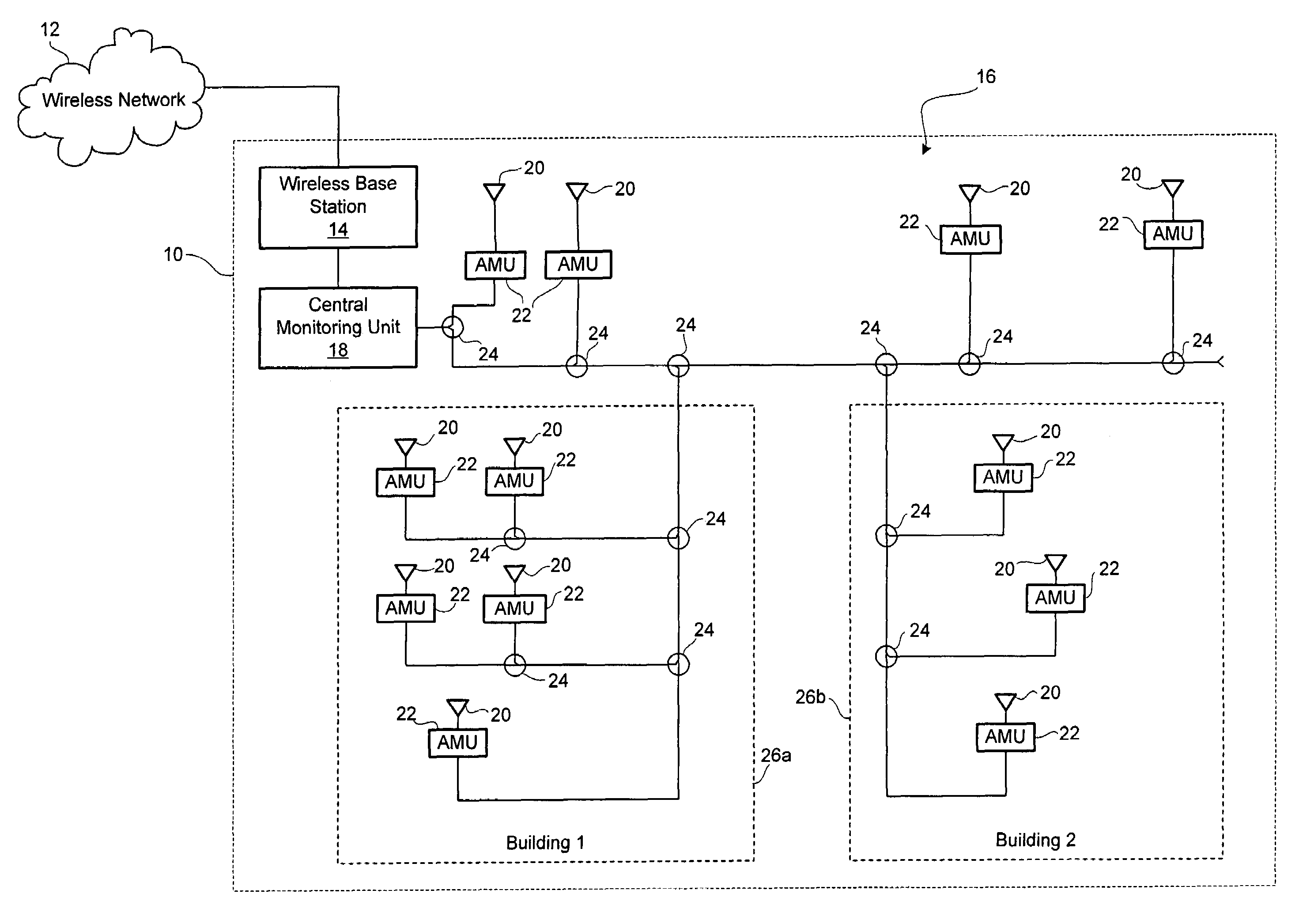
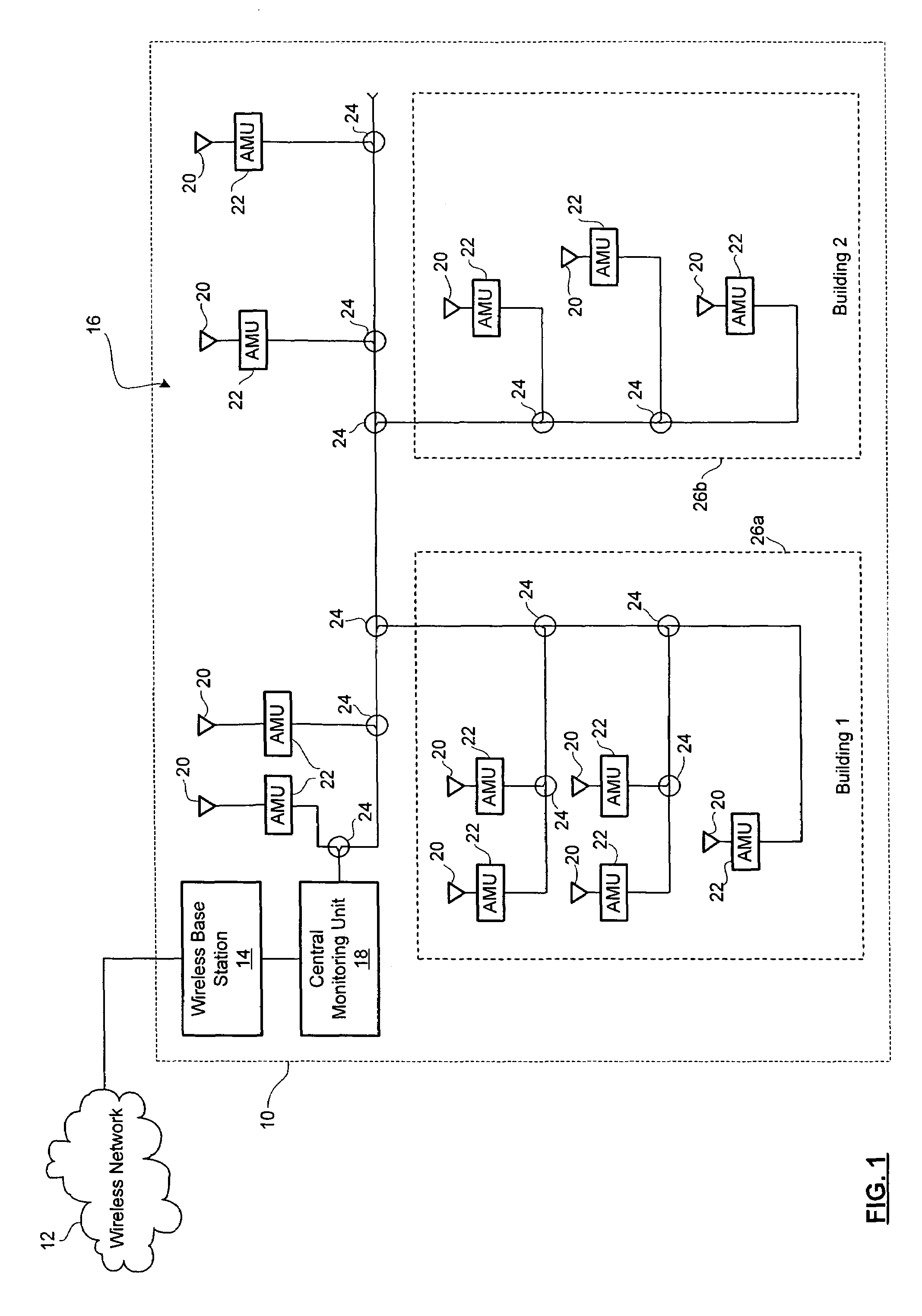
[0015]Reference is first made to FIG. 1, which shows a block diagram of a system for antenna fault monitoring in accordance with the present invention. A facility 10 has a wireless base station 14, which is coupled to a wireless network 12. The wireless network 12 may be a cellular network, a PCS network, a paging network, or other wireless communication network for interfacing with mobile devices. The wireless network 12 may operate using AMPS, DAMPS, NADC, CDMA, TDMA, GSM, iDEN or other modulation protocols.

[0016]The facility 10 may be an indoor facility, an outdoor facility or a mixture of enclosed and open-air spaces. Without limiting the generality of the foregoing, the facility 10 may for example, be a shopping centre, an underground concourse, a subway system, a stadium, a hotel, an office tower, an entertainment center, or a business or industrial complex. In the embodiment shown in FIG. 1, the facility 10 includes an exterior area, a first building 26a and a second building...


PUM


Abstract

A method and system for detecting whether an antenna is property connected to a distributed antenna network. The current drawn by the antenna is measured and compared against an expected current draw or reference level. The measured level of current drawn by the antenna is indicative of whether the antenna is properly connected or is disconnected. The comparison results may be used as the basis for creating a status message, which is then communicated to a central monitoring unit for each antenna. The central monitoring unit may generate appropriate alarms in response to a status message indicating a fault condition at a particular antenna.

Description

FIELD OF THE INVENTION[0001]The present invention relates to distributed antenna systems and, in particular, to monitoring antennas to detect a fault condition.BACKGROUND OF THE INVENTION[0002]Many facilities present problems for wireless RF communication signals and require that an in-facility signal distribution system be employed to provide adequate wireless reception and coverage within the facility. Signal distribution is often accomplished by providing an antenna distribution system that is coupled to a base station of the wireless communications system. The antenna distribution system typically includes a number of antennas distributed throughout the facility and connected to a base station via coaxial cables. The system may employ a tree-and-branch architecture, wherein uplink and downlink signals to and from the various antennas are combined using couplers.[0003]It was once thought that it was unnecessary to monitor the integrity of a distributed antenna system since it is ...

Claims


Application Information

Patent Timeline
Patent Type & Authority Patents(United States)
IPC IPC(8): G01R31/08
CPCH01Q3/267H04B17/12
Inventor GRAHAM, GERALDLIBER, PAUL
Owner P G ELECTRONICS
Why Eureka
Try Eureka