
Sensor arrangement and method for the installation and moving of this

a technology of sensors and moving parts, applied in seismology, seismology, instruments, etc., can solve the problems of increasing the installation time of sensors, requiring the use of large equipment, requiring energy consumption, and requiring large equipment, etc., and achieving the effect of reducing the installation time, reducing the difficulty of installation, and reducing the number of sensors

Active Publication Date: 2007-05-29
SEABED GEOSOLUTIONS
View PDF5 Cites 20 Cited by
  • Summary
  • Abstract
  • Description
  • Claims
  • Application Information

AI Technical Summary

Benefits of technology

[0012]The main object of the invention is, therefore, to provide an arrangement that provides for an effective, reliable seismic monitoring method for petroleum fields, both as an aid during the establishment phase and in the further management of the field resources throughout the life time of the field. The intention of the invention is to provide a substantial reduction of the disadvantages that may be related to known methods and equipment. More specifically it is an object to create a system that makes possible

Problems solved by technology

This solution may function well for installations with a limited time duration, in the order of one month, but it becomes less feasible when substantially longer installation times are required.
This may represent substantial and lasting environmental interventions in the seabed biotope, and require the use of large, energy consuming, and air pollutive equipment during the embedment process.
The cables cannot be laid over existing obstructions on the seabed or in areas where future underwater installations are planned.
Furthermore, it turns out that in practice, it is difficult to maintain / repair the buried parts of the cable system without having to dig them out again.
A cable system which is not maintained will typically detonate within a few years due to electric failure and water intrusion.
Depending on the type of failure in the cable, the failure may have consequences for parts of the cable that are downstream in relation to the position of the failure.
If one, on the other hand, moves a cable to the surface for maintenance and repairs, it will be a challenge replacing it later in the exactly same position as before, and with the same acoustic coupling to the seabed as the original coupling.
It will also imply substantial risk of damaging cables that must be raised up again.
From US patent publication U.S. Pat. No. 6,474,254 (WesternGeco, 2002) it is known to deploy cables with attached sensors in a network on the seabed, but this requires the application of a remotely operated vehicle (ROV), and provides no possibility for the repair of individual sensors.
This solution has not proven to be satisfactory from a deployment and application point of view.
This equipment does not satisfactorily provide the possibility for the placement in a substantially permanent network of sensor arrangements with a cable connection to the individual units.
Neither does this provide satisfactory possibilities for maintenance and repairs.

Method used


Image

  • Sensor arrangement and method for the installation and moving of this
  • Sensor arrangement and method for the installation and moving of this
  • Sensor arrangement and method for the installation and moving of this

Examples


Embodiment Construction

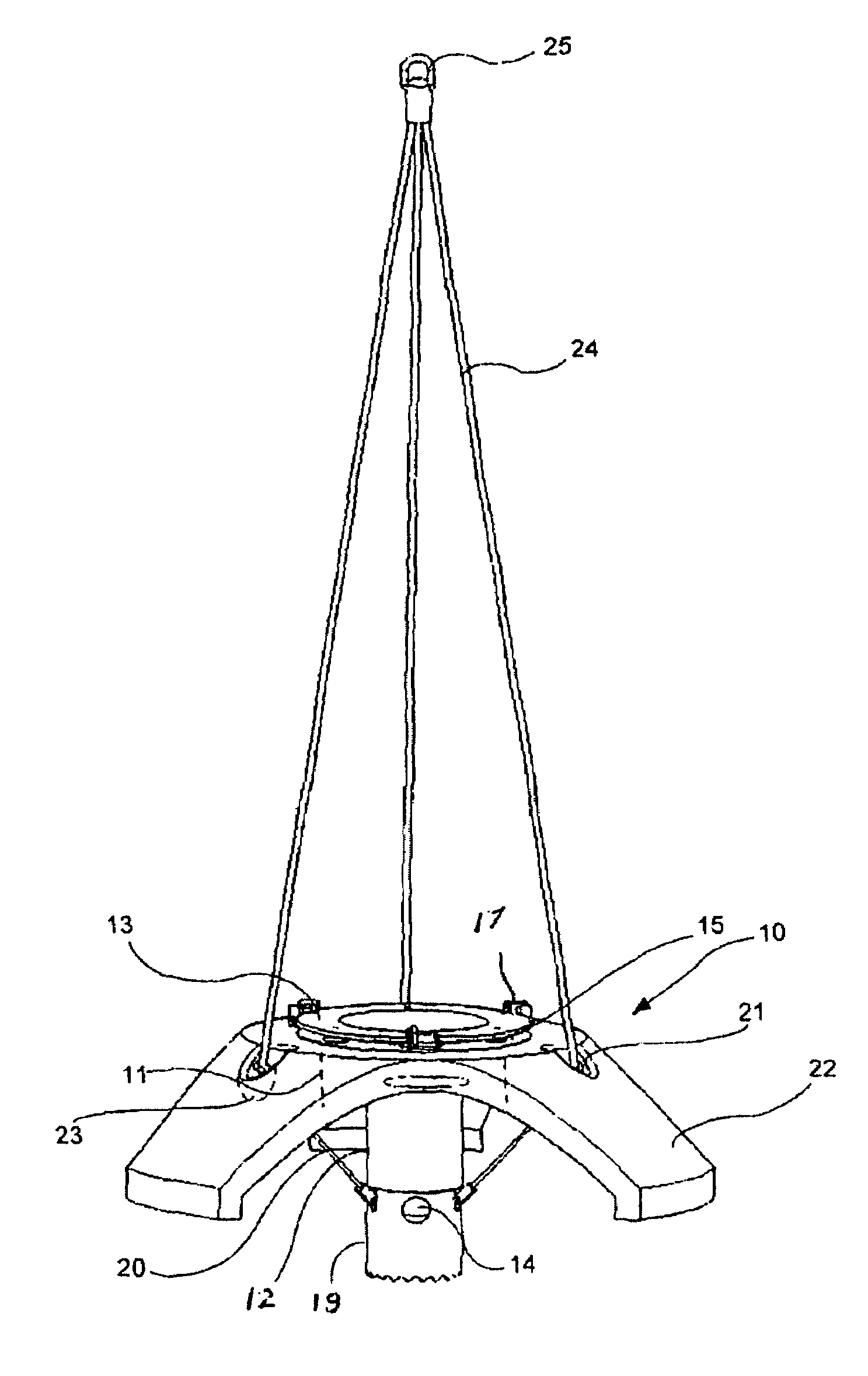
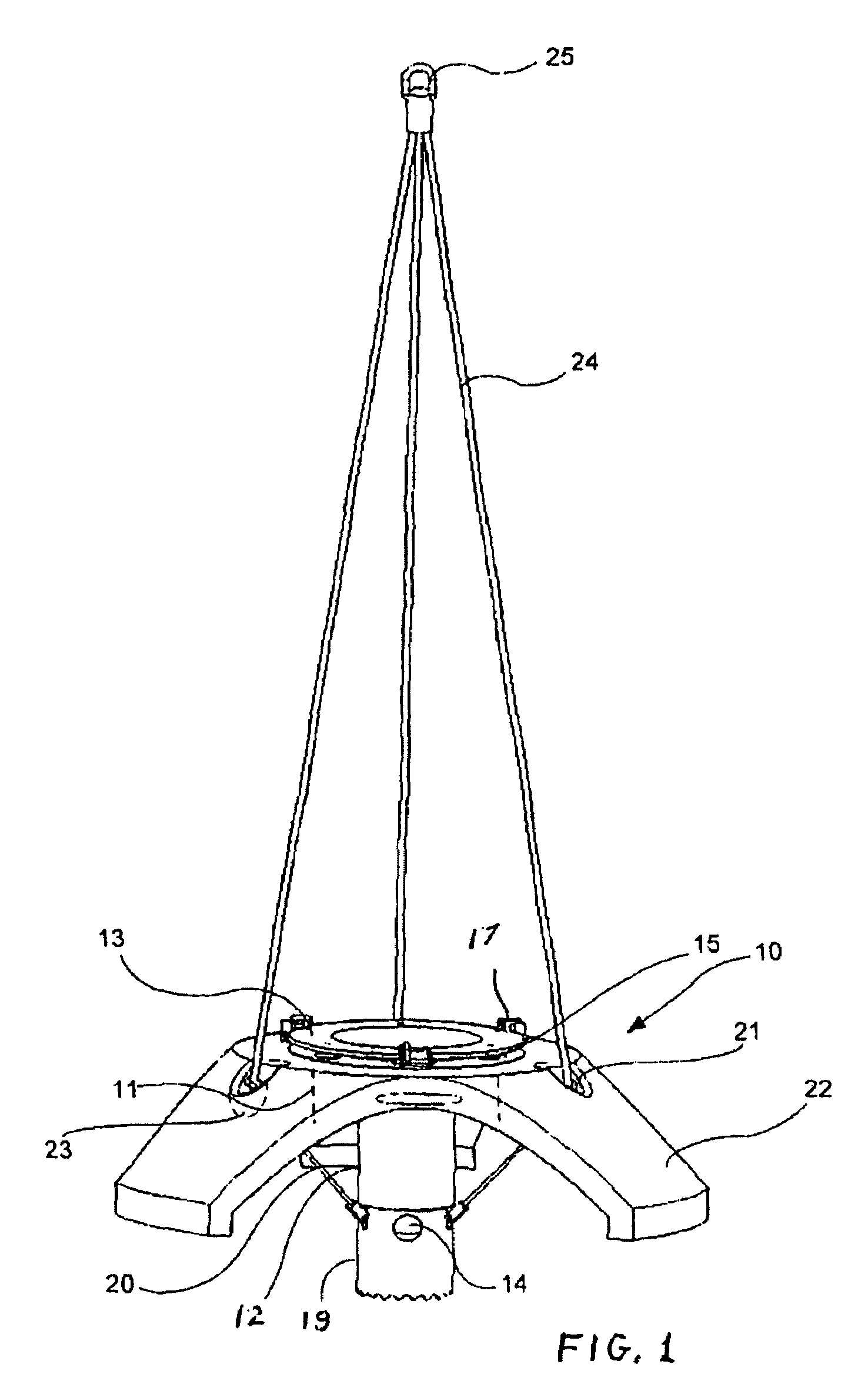
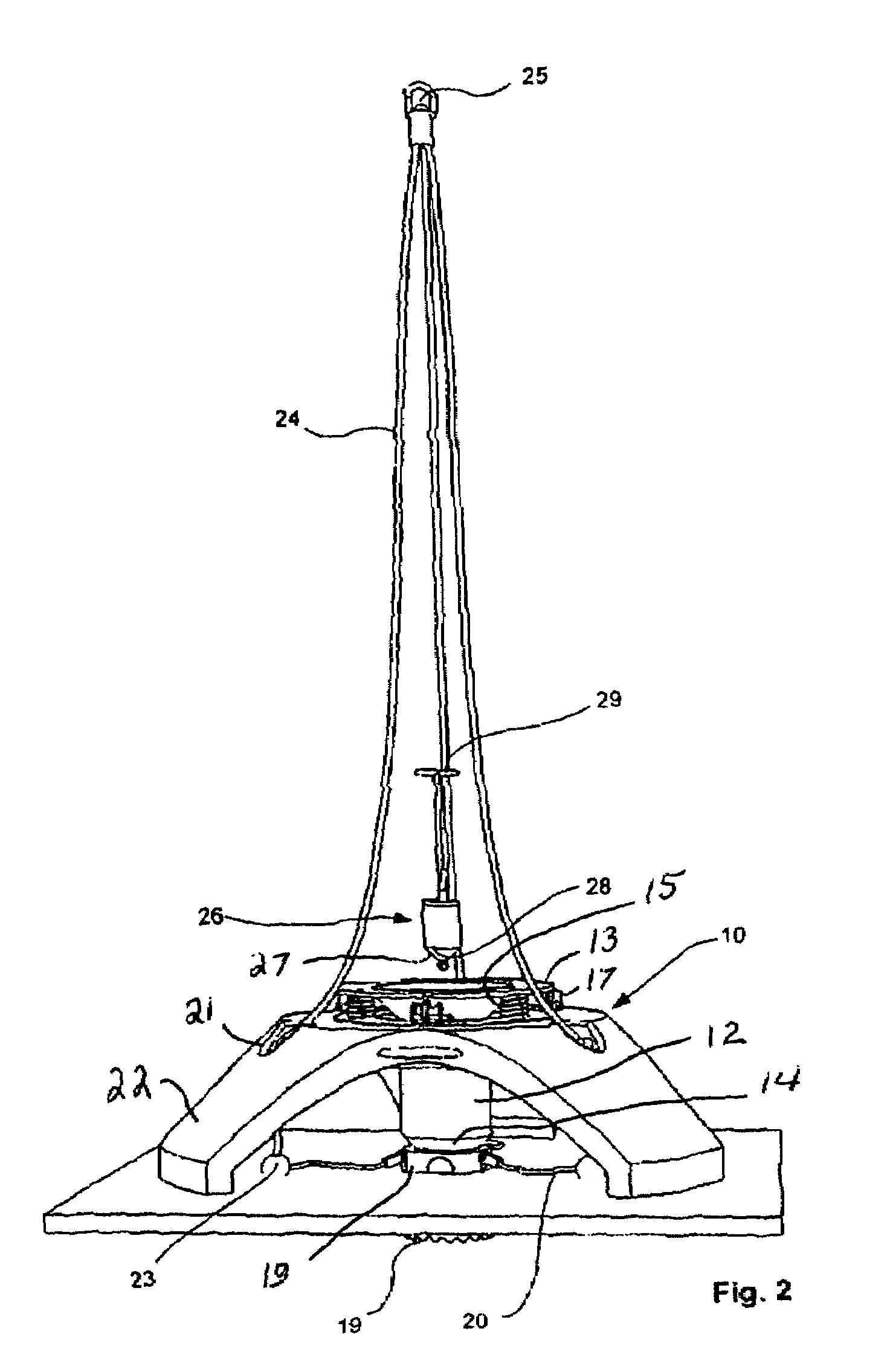
[0034]Referring to FIGS. 1–3, a sensor arrangement or sensor node is shown, with a carrier arrangement or carrier in the form of a three-legged stand 10 with a vertical main axis, made of, for instance, reinforced concrete. In a hole 11 along the main axis, a tube-shaped drawback 12 is placed, with a projection 13 on the top and a tapered, open constriction 14 at the bottom. The drawback 12 is held by four helical springs 15 (FIG. 3), placed between the projection 13 and recesses 16 in the top of the stand 10. At the starting point, the drawback is biased downwardly against the springs, by releasable locking lugs 17, which are secured to brackets 18 on the top side of the stand 10.

[0035]At the lower edge of the tapered constriction 14, a tube-shaped blade 19 with a vertical main axis is placed in mechanical contact with the constriction 14. The shape of the top of the blade 19 is adapted to the drawback 12, the main axes are coincident and relative rotation between these parts are h...


PUM


Abstract

Arrangement for use for seismic surveys of geological formations in a seabed, where a plurality of such arrangements, which are provided with sensor units 26, are placed on the seabed for collecting pressure waves and shear waves reflected from the geological formations. There exist arrangements for transferring seismic data to a surface receiver placed on a vessel, an offshore installation, or an onshore installation. Each sensor unit 26 is held by a carrier 10 and is connected to a cylindrically skirt-shaped structure 19 adapted to be led down into the seabed, and each sensor unit 26 comprises at least one geophone. The carrier 10 comprises a holder 12 for the cylindrically skirt-shaped structure 19, which structure 19 shall penetrate down into the seabed, as this holder 12 is adapted to be moved between a lower position and an upper position, to be able to be mechanically released from the skirt-shaped structure 19.

Description

BACKGROUND OF THE INVENTION[0001]1. Field of the Invention[0002]The present invention relates to a sensor arrangement as indicated in the introduction of claim 1, for use on the seabed. Such sensor arrangements may be used, permanently or temporarily installed on the seabed, for surveillance of petroleum reservoirs and adjacent well systems.[0003]The invention also relates to a method for the installation and moving of seismic sensor arrangements on the seabed.[0004]2. Description of Related Art[0005]To be able to perform seismic surveys of formations below the sea, a plurality of sensor nodes are placed on the seabed, preferably in a regular disposition. These sensor nodes must be in contact with a solid medium, leading to requirements for the deployment operation. From Norwegian Patent Application No. 20025896, an arrangement is known, in which to each sensor node is connected a remotely operated control and registration unit for telemetric transmission of data to a control center...

Claims


Application Information

Patent Timeline
Patent Type & Authority Patents(United States)
IPC IPC(8): G01V1/38G01SG01V1/20
CPCG01V1/20G01V1/3852
Inventor NAS, JOHAN FREDRIK
Owner SEABED GEOSOLUTIONS
Learn More