Sensor apparatus and self-propelled floor cleaning appliance having a sensor apparatus

a technology of sensor apparatus and floor cleaning appliance, which is applied in the direction of carpet cleaners, instruments, program control, etc., can solve the problems of insignificant production cost and the difficulty of detecting the intensity of reflected infrared radiation, and achieve the effect of reliably detecting the risk of the floor cleaning appliance falling, low cost production, and reliable detection of the risk of the appliance falling

Inactive Publication Date: 2007-06-05
ALFRED KARCHER GMBH & CO KG
View PDF23 Cites 156 Cited by
  • Summary
  • Abstract
  • Description
  • Claims
  • Application Information

AI Technical Summary

Benefits of technology

[0011]To achieve a configuration of the sensor apparatus which is compact and simple to handle in particular for assembly purposes, it is expedient if the reception unit and the first and second transmission units are integrated in a housing of the sensor apparatus.
[0024]The floor cleaning appliance preferably comprises at least one supporting roller which is disposed between the front sensor apparatuses and the drive wheels, based on a main direction of movement of the floor cleaning appliance. In this context, it is particularly expedient if the distance between the supporting rollers and the front sensor apparatuses, as seen in the main direction of movement, corresponds to at least a quarter of the distance between the front sensor apparatuses and the drive wheels. This makes it possible to ensure that the floor cleaning appliance can be stopped in good time when the floor cleaning appliance is approaching a down step before the supporting roller, which is positioned in front of the drive wheels in the direction of movement, moves beyond the edge of the step.

Problems solved by technology

Sensor apparatuses of this type have the difficulty that the intensity of the reflected infrared radiation is dependent not only on the distance between the sensor apparatus and the floor surface, but also on the direction of the radiation reflected from the floor surface.
However, position-dependent sensor apparatuses of this type are characterized by considerable production difficulties and are therefore associated with by no means insignificant production costs.

Method used


Image

  • Sensor apparatus and self-propelled floor cleaning appliance having a sensor apparatus
  • Sensor apparatus and self-propelled floor cleaning appliance having a sensor apparatus

Examples


Embodiment Construction

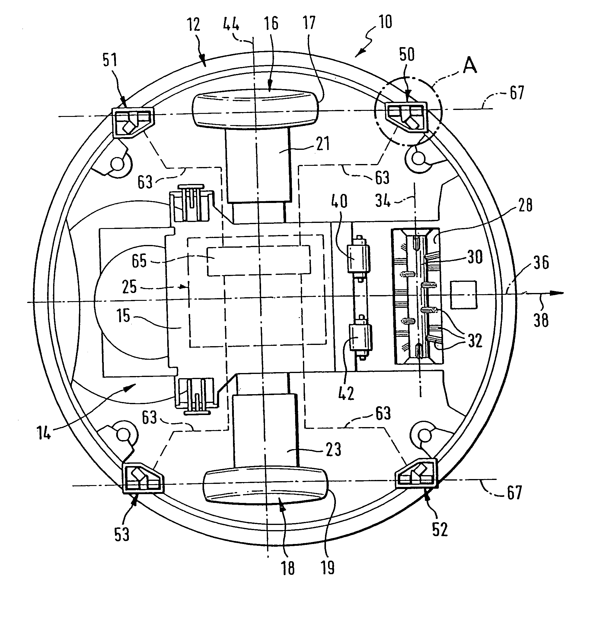
[0028]FIG. 1 diagrammatically depicts a view of a self-propelled and self-steering floor cleaning appliance, which is denoted overall by reference numeral 10, from below. The floor cleaning appliance comprises a housing 12, which forms a chassis 14, onto the top side of which a housing cover (not shown in the drawing) can be fitted. Two drive wheels 16, 18, which each have a tread 17 and 19, respectively, by means of which the drive wheels 16, 18 are in contact with a floor surface that is to be cleaned, are rotatably mounted on the chassis 14.

[0029]The drive wheels 16, 18 each have an associated electric drive motor 21 and 23, respectively, which is fixed to the underside of the chassis 14. The two drive motors 16, 18 are electrically connected to control electronics 25, positioned on the top side of the chassis 14, and to a rechargeable battery, which is known per se and is therefore not shown in the drawing.

[0030]On its top side, the chassis 14 carries a suction unit, which is kn...


PUM


Abstract

The invention relates to a sensor apparatus for a self-propelled floor cleaning appliance for detecting a down step, having a transmission unit and a reception unit for infrared radiation and having evaluation electronics for evaluating the intensity of the radiation received. To develop the sensor apparatus in such a manner that a down step or a steep downslope of the floor surface can be determined more reliably, while the sensor apparatus can be produced at low cost, according to the invention it is proposed that the sensor apparatus has the reception unit and a first and a second transmission unit, the second transmission unit being disposed at a distance from a connecting straight line running through the reception unit and the first transmission unit. The invention also proposes a floor cleaning appliance having a sensor apparatus of this type.

Description

[0001]This application is a continuation of international application number PCT / EP 03 / 06223 filed on Jun. 13, 2003.[0002]The present disclosure relates to the subject matter disclosed in international application number PCT / EP 03 / 06223 of Jun. 13, 2003 and German application number 102 31 386.5 of Jul. 8, 2002, which are incorporated herein by reference in their entirety and for all purposes.BACKGROUND OF THE INVENTION[0003]The invention relates to a sensor apparatus for a self-propelled floor cleaning appliance for detecting a down step with a transmission unit for emitting infrared radiation and a reception unit for receiving infrared radiation and with evaluation electronics for evaluating the intensity of the radiation received.[0004]Moreover, the invention relates to a self-propelled and self-steering floor cleaning appliance having a chassis and an electrical drive unit with electrical control unit and drive wheels mounted on the chassis, and with a sensor apparatus of this t...

Claims


Application Information

Patent Timeline
Patent Type & Authority Patents(United States)
IPC IPC(8): A47L11/00G01S7/481G01S17/87G01S17/875G01S17/88
CPCG01S7/4813G01S17/875G01S17/88G01S17/87A47L2201/04
Inventor DIEHL, RALPHBENZLER, GOTTFRIEDKEPPLER, JOACHIMJANZEN, JAKOB
Owner ALFRED KARCHER GMBH & CO KG
Why Eureka
Try Eureka