System and method to control transitions in the number of cylinders in a hybrid vehicle

a hybrid vehicle and transition control technology, applied in the direction of electric control, machines/engines, output power, etc., can solve the problems of degrading vehicle feel, continually draining the battery, and affecting the fuel economy of the vehicle, so as to achieve the effect of increasing fuel economy

Active Publication Date: 2007-06-05
FORD GLOBAL TECH LLC
View PDF8 Cites 67 Cited by
  • Summary
  • Abstract
  • Description
  • Claims
  • Application Information

AI Technical Summary

Benefits of technology

[0002]Variable displacement engine have been used where one or more cylinder is deactivated (e.g., by closing intake and exhaust valves). In this way, increased fuel economy can be obtained during engine operating conditions that do not require full cylinder operation.
[0005]In one example, at least some of the above disadvantages may be overcome by a vehicle system, comprising: a engine capable of disabling and enabling at least one cylinder; a motor coupled to said engine capable of absorbing torque and providing torque; and a controller for disabling and enabling said at least one cylinder, and during at least one of disabling and enabling, varying torque of said motor to compensate for transient changes in engine output torque caused by said one of disabling and enabling.
[0006]In this way, it may be possible to provide improved torque control during variation in the number of cylinders carrying out combustion. Further, such transitions may be performed with less energy loss due to spark retard. Further still, such transitions may be performed to increase stored energy. Finally, such transitions may be performed based on battery status to provide improved hybrid vehicle performance.

Problems solved by technology

The inventors herein have recognized a disadvantage with such an approach.
In particular, US 2004 / 0035113 generally requires consistent application of torque from the motor during cylinder deactivation conditions; however, this can continually drain the battery, especially during vehicle towing conditions or during long vehicle climbs.
Furthermore, the inventors herein have also recognized that the transitions according to US 2004 / 0035113 may also result in degraded vehicle feel since a substantially constant motor torque is used, relying on rapid throttle changes to handle the torque disturbance.
Specifically, even rapid throttle changes may be inadequate to provide acceptable vibration and drive feel during the transition.

Method used


Image

  • System and method to control transitions in the number of cylinders in a hybrid vehicle
  • System and method to control transitions in the number of cylinders in a hybrid vehicle
  • System and method to control transitions in the number of cylinders in a hybrid vehicle

Examples


Embodiment Construction

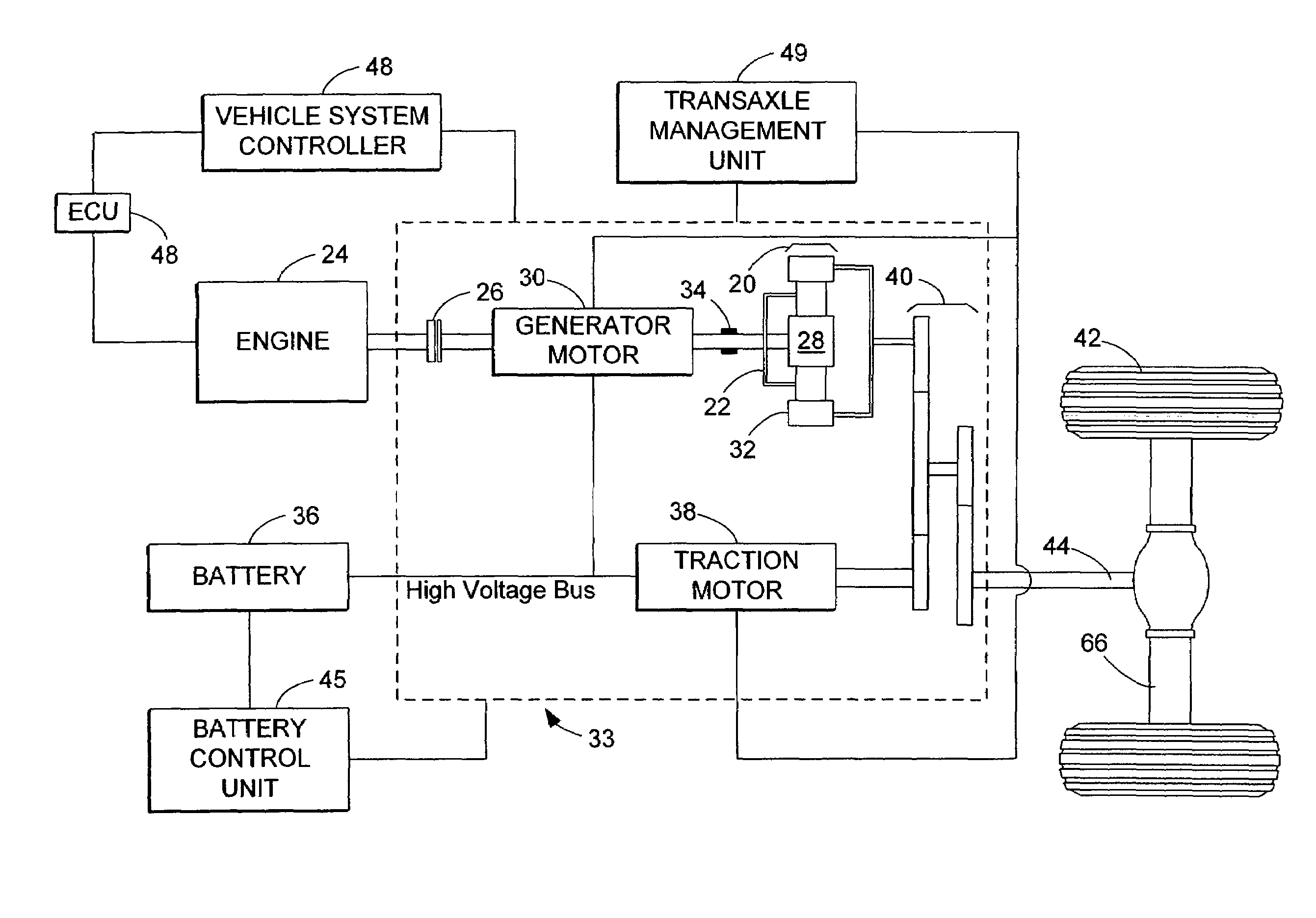
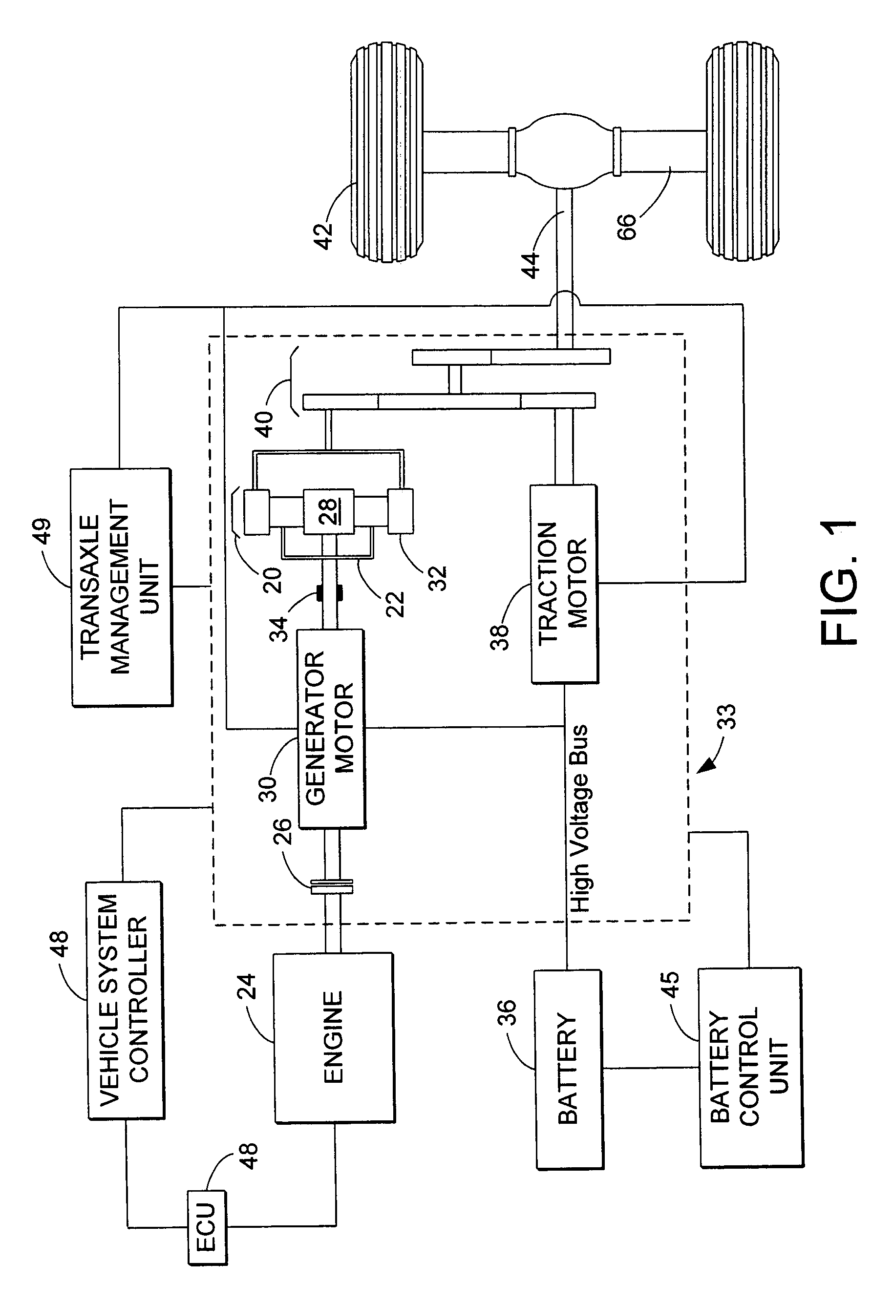
[0012]The present disclosure relates to electric vehicles and, more particularly, hybrid electric vehicles (HEVs). FIG. 1 demonstrates just one possible configuration, specifically a parallel / series hybrid electric vehicle (split) configuration.

[0013]In an HEV, a planetary gear set 20 mechanically couples a carrier gear 22 to an engine 24 via a one way clutch 26. The planetary gear set 20 also mechanically couples a sun gear 28 to a generator motor 30 and a ring (output) gear 32. The generator motor 30 also mechanically links to a generator brake 34 and is electrically linked to a battery 36. A traction motor 38 is mechanically coupled to the ring gear 32 of the planetary gear set 20 via a second gear set 40 and is electrically linked to the battery 36. The ring gear 32 of the planetary gear set 20 and the traction motor 38 are mechanically coupled to drive wheels 42 via an output shaft 44.

[0014]The planetary gear set 20, splits the engine 24 output energy into a series path from th...


PUM


Abstract

A vehicle system is disclosed. The system include a engine capable of disabling and enabling at least one cylinder; a motor coupled to said engine capable of absorbing torque and providing torque; and a controller for disabling and enabling said at least one cylinder, and during at least one of disabling and enabling, varying torque of said motor to compensate for transient changes in engine output torque caused by said one of disabling and enabling.

Description

FIELD[0001]The present application relates to variable displacement engines coupled in hybrid powetrains of vehicles.BACKGROUND AND SUMMARY[0002]Variable displacement engine have been used where one or more cylinder is deactivated (e.g., by closing intake and exhaust valves). In this way, increased fuel economy can be obtained during engine operating conditions that do not require full cylinder operation.[0003]Vehicle system with variable displacement capabilities have also been described having hybrid powertrains. For example, US 2004 / 0035113 describes an approach where cylinder deactivation operation can be extended by providing additional torque from an electric motor. Further, activation / deactivation transitions are described using changes in throttle position with motor assist require before, during, and after the transition.[0004]The inventors herein have recognized a disadvantage with such an approach. In particular, US 2004 / 0035113 generally requires consistent application o...

Claims


Application Information

Patent Timeline
Patent Type & Authority Patents(United States)
IPC IPC(8): F02B75/06F02D17/02
CPCB60K6/445B60W10/06B60W10/08B60W20/00F02D13/06F02D17/02F02D41/0087F02D41/1497B60K1/02B60W2510/244F02D41/307F02D2250/18F02D2250/21F02D2250/24Y02T10/6286Y02T10/18Y02T10/6239Y02T10/12Y02T10/62B60W20/13
Inventor PALLETT, TOBIASKERNS, JAMESSURNILLA, GOPICHANDRA
Owner FORD GLOBAL TECH LLC
Why Eureka
Try Eureka