Grommet or fill valve for an aerosol container

a technology for aerosol containers and fill valves, which is applied in the field of aerosol dispensing containers, can solve the problems of reducing the possibility of propellant leakage from containers, reducing warranty returns and associated costs of replacing non-functioning or “dead” containers, and improving the cross-linking. , the effect of improving the sealing ability

Active Publication Date: 2007-06-05
BALL METALPACK AEROSOL CONTAINER LLC
View PDF8 Cites 24 Cited by
  • Summary
  • Abstract
  • Description
  • Claims
  • Application Information

AI Technical Summary

Benefits of technology

[0012]The present invention is directed to an improved fill valve for use in an aerosol container to provide a better sealing capability. The fill valve is made using a flashless injection molding process rather than the compression molding process previously used. As part of this process, both the mold cavity and molding material are heated to elevated temperatures and this significantly improves the cross-linking which occurs during the molding process. Further, a section of the backside of the sealing area of the fill valve now has a recessed portion that improves flexing of the seal after propellant is injected into the container, thereby creating a more responsive seal. Information about the fill valve is now engraved on an out-of-the-way surface of the valve so to facilitate conveying of the valve during manufacture of a container.
[0013]This improved fill valve has a number of advantages over previous valves. One is a fill valve with more consistent dimensional and operational characteristics than previous fill valves. Importantly, the improved fill valve provides a more capable seal, and a valve less prone to the formation of leak paths through the valve. This significantly reduces the possibility of propellant leakage from a container, even containers with long shelf lives. This, in turn, reduces warranty returns and the associated costs of replacing a non-functioning or “dead” container. Additionally, because of the improved sealing capability, the reduction in leakage reduces pollution. It may also be possible to reduce the amount of propellant injected into a container during filling because, with less leakage, more propellant will remain in the container.
[0014]The elimination of unnecessary raised lettering also now makes it easier to handle and move significant volumes of fill valves during fabrication of a container.

Problems solved by technology

This significantly reduces the possibility of propellant leakage from a container, even containers with long shelf lives.
This, in turn, reduces warranty returns and the associated costs of replacing a non-functioning or “dead” container.

Method used


Image

  • Grommet or fill valve for an aerosol container
  • Grommet or fill valve for an aerosol container
  • Grommet or fill valve for an aerosol container

Examples


Embodiment Construction

[0022]The following detailed description illustrates the invention by way of example and not by way of limitation. This description will clearly enable one skilled in the art to make and use the invention, and describes several embodiments, adaptations, variations, alternatives and uses of the invention, including what I presently believe is the best mode of carrying out the invention. As various changes could be made in the above constructions without departing from the scope of the invention, it is intended that all matter contained in the above description or shown in the accompanying drawings shall be interpreted as illustrative and not in a limiting sense.

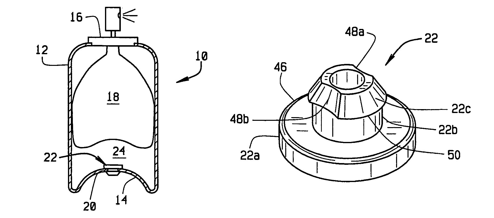
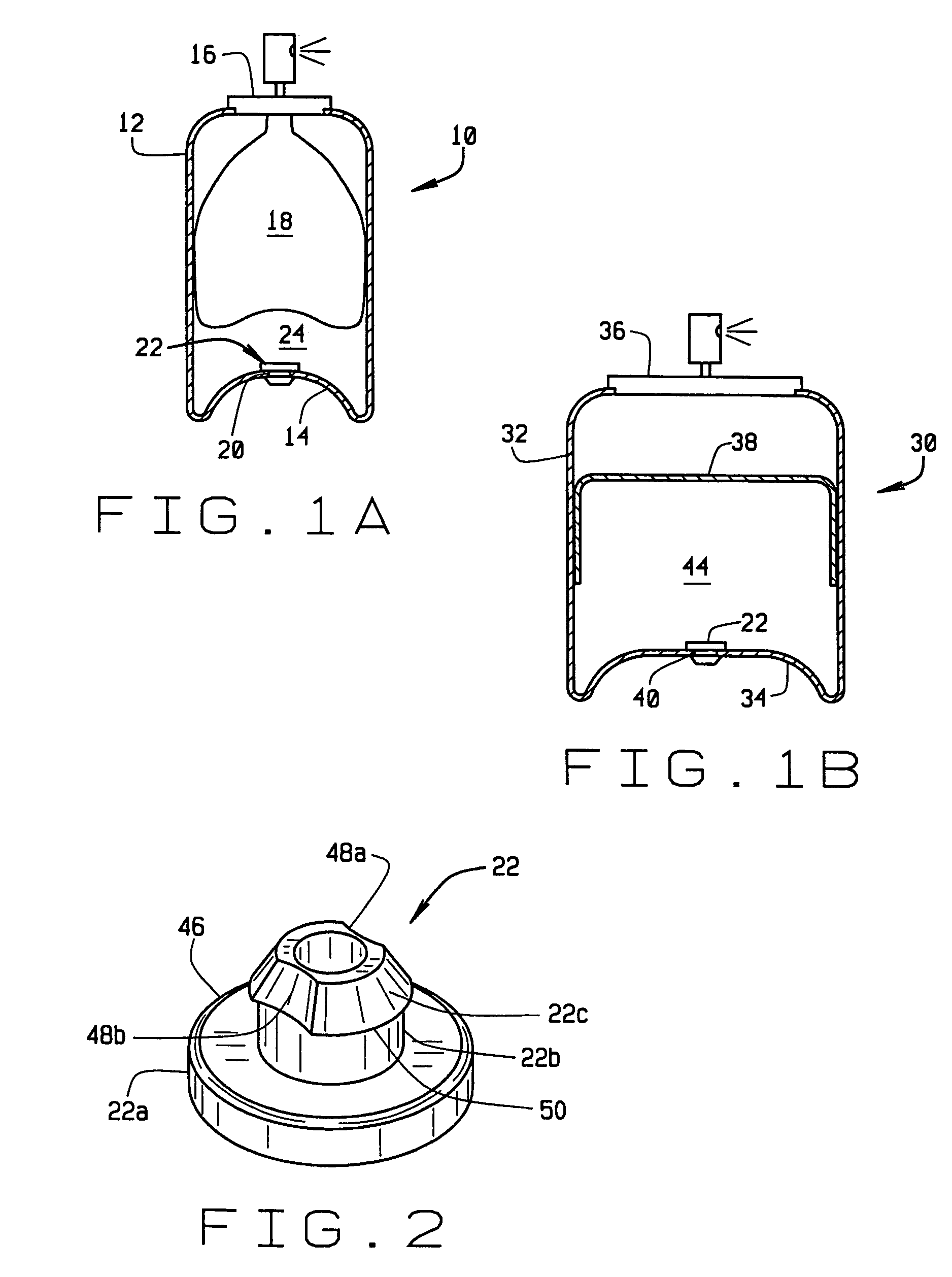
[0023]Referring to FIG. 1A, an aerosol container 10 comprises a cylindrically shaped body 12, a bottom, dome shaped end piece 14, and an upper cap / valve assembly 16. A product bag 18 is disposed in the container for dispensing a fluent product, and for this purpose, the container is filled with a propellant material, under pre...


PUM

PropertyMeasurementUnit
diameteraaaaaaaaaa
pressureaaaaaaaaaa
distanceaaaaaaaaaa

Abstract

The present invention is directed to an improvement for a fill valve (22) for an aerosol container (10, 30) to provide better sealing capability. The fill valve is made using a flashless injection molding process in which both the mold cavity and molding material are heated to elevated temperatures to significantly improve cross-linking which occurs during the molding process. A backside (22a) of the fill valve now has a recessed portion (56) to facilitate ejection of the valve from a mold so leak paths are not created due to the forces applied to the valve during its extraction from the mold. The recessed portion reduces the amount of material required to make the fill valve and makes the fill valve flexible to aid in providing a good seal against leakage of a propellant from the container after filling.

Description

CROSS REFERENCE TO RELATED APPLICATIONS[0001]Provisional patent application 60 / 645,679 filed Jan. 21, 2005STATEMENT REGARDING FEDERALLY SPONSORED RESEARCH OR DEVELOPMENT[0002]N / ABACKGROUND OF THE INVENTION[0003]This invention relates to aerosol dispensing containers incorporating a bag holding a product to be dispensed and a propellant chamber formed between the bag and container sidewall, and more particularly, to an improved grommet or fill valve (sometimes also referred to as an umbrella valve or seal valve) by which a propellant is introduced into the container and retained therein until all the product in the container is dispensed. Alternately, the container may employ a piston on one side of which is the product to be dispensed and on the other side of which is the propellant chamber. Again, the improved fill valve allows a propellant to be introduced into the chamber and retained therein until all the product is dispensed.[0004]Certain types of aerosol containers include a c...

Claims


Application Information

Patent Timeline
Patent Type & Authority Patents(United States)
IPC IPC(8): B65B1/04B29D99/00
CPCB65D83/42B29C45/0001B29K2021/00B29L2031/7506
Inventor MACKENZIE, ROBERTFERNANDES, MICHELFIDALGO, DIAMANTINOMALONE, CAROL
Owner BALL METALPACK AEROSOL CONTAINER LLC
Why Eureka
Try Eureka