Structure for a seat supporting frame of a chair

a technology for supporting frames and chairs, applied in the field of chair supporting frames, can solve the problems of reduced lifespan, thereby total damage of chairs, and reduced lifespan, and achieve the effect of reducing lifespan and facilitating welding horizontal supports

Active Publication Date: 2007-06-05
SPEC SEATS TECH
View PDF9 Cites 19 Cited by
  • Summary
  • Abstract
  • Description
  • Claims
  • Application Information

AI Technical Summary

Benefits of technology

[0011]A vertical support piece is riveted onto the seating frame by means of a stud, and the upper section of the vertical support piece is welded on the inner side of a front leg. A stop abutment is extended along the lower part of the vertical support piece, which can be firmly abutted against the inside edge of the curved section on the two ends of the horizontal support and is not overextending past the curved section, when the chair is unfolded. Because the space between the curved section of the horizontal support and the edge surface of the seat is small, the stop abutment, which is firmly abutted and positioned on the horizontal support, has only a small offset gap; therefore, the stop abutment would only shift a tiny amount of distance, and would not move past the surface of the curved section of the horizontal support even when the chair is to be supporting a very heavy load, or that the user on the chair changes his posture again and again.
[0012]For the horizontal support according to the present invention because of having flat surfaces at the two ends, it is easier to weld the horizontal support with the front leg and to weld more tightly than the conventional horizontal support, whose two ends extend to the front leg and must be welded along the curled edge of the front leg. The welding technique for the conventional horizontal support is difficult, and the welded part is not very firm. In addition, the raised curved surface formed at the curved section at the end of the horizontal support according to the present invention can prevent the stop abutment from moving beyond the outside of the ends. Compared to the horizontal support in the present invention, the conventional horizontal support does not have the curved section, and the stop abutment would shift, tilt, and move toward the outer sides of the front leg when the user is moving frequently on the chair. Thus the entire seating frame will be loosened, and would be unsuitable for sitting. In more severe cases, the curled edge may even be fractured, and cannot be positioned and firmly abutted against the horizontal support. As a result, the chair is no longer usable, and has its lifespan reduced.
[0013]The loosening and sliding due to the horizontal support and the stop abutment moving passing the outside may not have occurred instantly, but instead can be accumulated over a longer period of time. Furthermore, the loosening can also be due to the user on the chair changing his postures more frequently. As a result, the user's safety must be considered in order to avoid accidents during the manufacturing process of the chair.

Problems solved by technology

As a result, the chair is thereby completely damaged, become useless, and has its lifespan reduced.
The other problem to be solved is to ensure the stop abutment to be consistently firmly abutting against the inner portion of the curved section on the two ends of the horizontal support for the proper support, balancing, and placement on the horizontal support.

Method used


Image

  • Structure for a seat supporting frame of a chair
  • Structure for a seat supporting frame of a chair
  • Structure for a seat supporting frame of a chair

Examples


Embodiment Construction

[0022]Reference will now be made in detail to embodiments of the present invention, examples of which are illustrated in the accompanying drawings. The present invention will be apparent to those skilled in the art by reading the following detailed description of a preferred embodiment and those skilled in the art can operate it according to the reference.

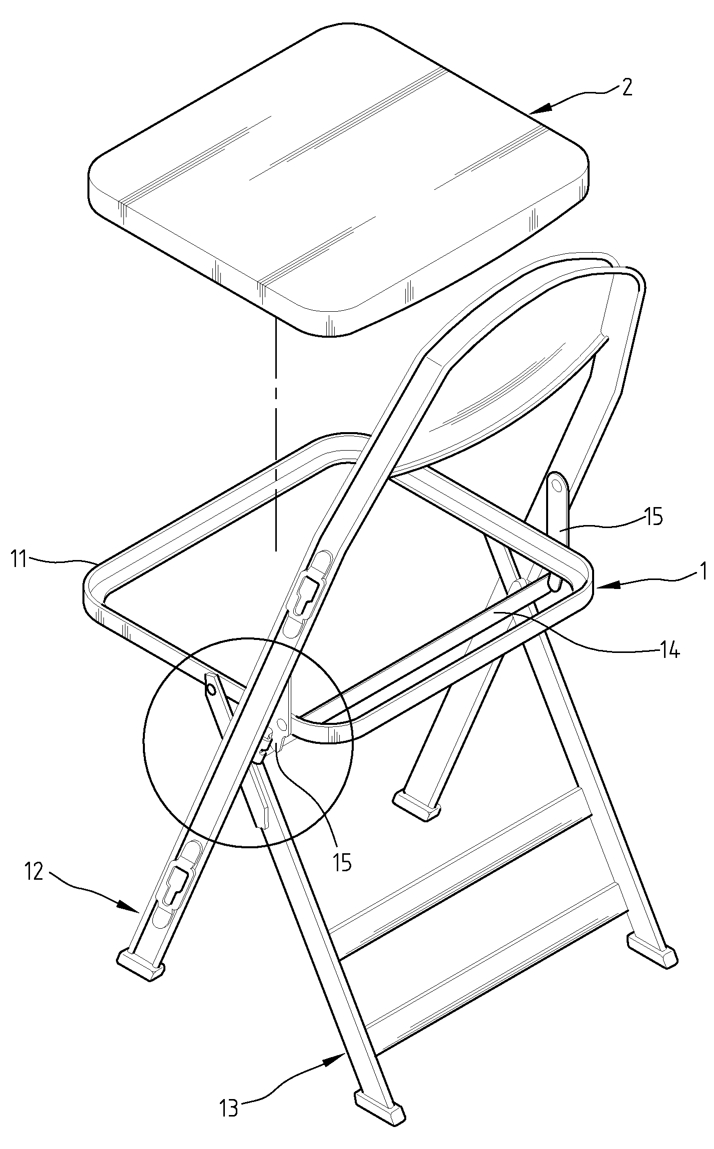
[0023]The present invention relates to an improved structure for a seat supporting frame of the folding chair. FIG. 2 shows the exploded drawing of a folding chair 1 and a seat 2 in accordance with the preferred embodiment of the present invention. A folding chair 1 body comprises a seating frame 11 on which a seat 2 is located, a plurality of front legs 12 and back legs 13 mounted on the two sides of the seating frame 11, and a horizontal support 14 set horizontally between the front legs 12. A vertical support piece 15 is formed between the side of the seating frame 11 and the side of the front leg 12. A stop abutment 151 is form...


PUM


Abstract

An improved structure for a seat supporting frame of a chair includes a seat, front legs and back legs mounted on the two sides, a horizontal support having flattened ends and forming a bent section. The bent section is welded with the inner side of the front leg. The two ends of the bent corners are formed with a curved section. The sides of the seat has vertical support pieces, one end of which is set on the side of the seating frame, and the other end is connected to the front leg. A stop abutment, mounted on the lower section of the vertical support piece, is firmly abutted to the inner side of the curved section of the horizontal support, so as to prevent it from sliding and fracture. The horizontal support, the front leg, the vertical support piece, and the stop abutment are held together tightly.

Description

BACKGROUND OF THE INVENTION[0001]1. Field of the Invention[0002]The present invention is related to an improved structure for a seat supporting frame of a chair, especially is related to having a horizontal a support, front leg, a vertical support piece, and a stop abutment to be held together secure and tightly, and thereby preventing the chair from loosening because of having a heavy people sitting in the chair.[0003]2. The Prior Arts[0004]With reference to FIG. 1 and FIG. 1A, which is the partial enlarged view showing the horizontal support A, the front leg B, the vertical support piece C, and the stop abutment C1 in the conventional folding chair, the seat supporting spots of the conventional folding chair are located between a seat D and a back leg E, the seat D and the stop abutment C1, the seat D and the horizontal support A. So the joining together and interactions between the four parts is important.[0005]It is observed that the stop abutment C1 connected to the vertical su...

Claims


Application Information

Patent Timeline
Patent Type & Authority Patents(United States)
IPC IPC(8): A47C4/48
CPCA47C4/24
Inventor LIN, MEI CHUENWANG, TZU MEI
Owner SPEC SEATS TECH
Why Eureka
Try Eureka