Roots vacuum pump

a vacuum pump and root technology, applied in the direction of rotary/oscillating piston pump components, machines/engines, liquid fuel engines, etc., can solve the problems of reducing volumetric efficiency and mechanical efficiency, unable to operate the pump, and producing loud noise of 90 db, so as to reduce the temperature of the whole pump, improve the efficiency of volumetric efficiency and energy saving, and reduce the noise produced during the pump operation

Active Publication Date: 2007-06-05
ANLET CO LTD
View PDF15 Cites 37 Cited by
  • Summary
  • Abstract
  • Description
  • Claims
  • Application Information

AI Technical Summary

Benefits of technology

[0010]According to the foregoing Roots vacuum pump, the volumetric efficiency and energy saving can be improved and noise produced during operation of the pump can be reduced. Furthermore, the temperature of the whole pump can be decreased.

Problems solved by technology

Consequently, the pump cannot operate.
These pumps result in reductions in volumetric efficiency and mechanical efficiency and production of loud noise of 90 dB or above.
Such installation increases the costs, resulting in diseconomy.
Furthermore, a high-temperature gas caused by compression leaks little by little through a minute gap inevitably defined by the inner peripheral wall and rotor lobes to the suction side.
This results in a reduction in the mechanical efficiency of the vacuum pump and deterioration in the temperature characteristic.

Method used


Image

  • Roots vacuum pump
  • Roots vacuum pump
  • Roots vacuum pump

Examples


Embodiment Construction

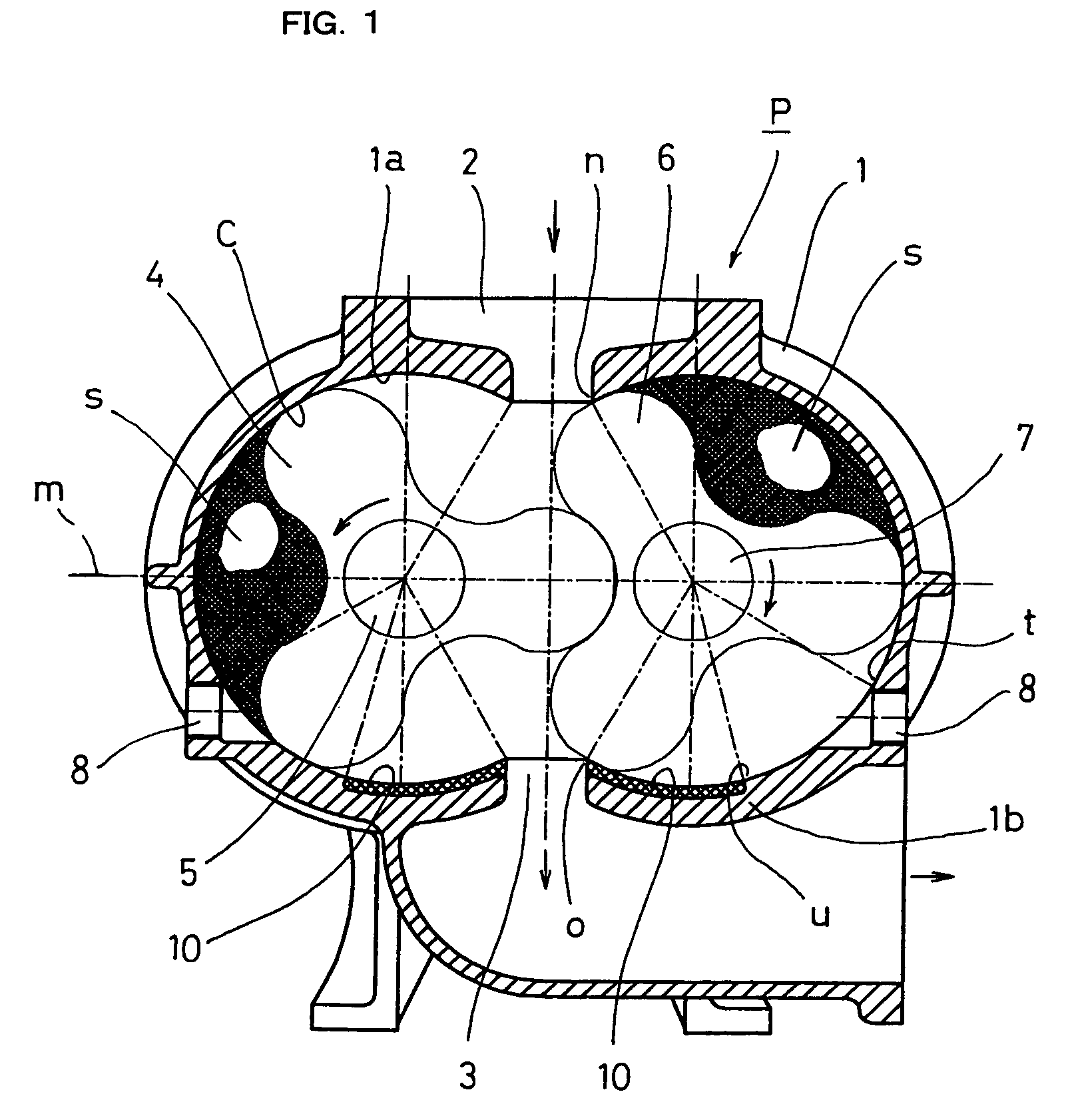
[0016]One embodiment of the present invention will be described with reference to the accompanying drawings. Referring to FIG. 1, a here-lobed Roots vacuum pump P includes a casing 1 formed with an inlet port 2 and an outlet port 3. A pair of three-lobed rotors 4 and 6 are provided in the casing 1 so as to be rotatable in opposite directions respectively. The rotors 4 and 6 are rotated so that the inlet and outlet ports 2 and 3 are prevented from communicating with each other, so that air is sucked through the inlet port 2 and the suck air is discharged through the outlet port 3. A small gap C having a predetermined dimension is defined between an inner wall surface 1a of the casing 1 and apex of each rotor lobe as well known in the art.

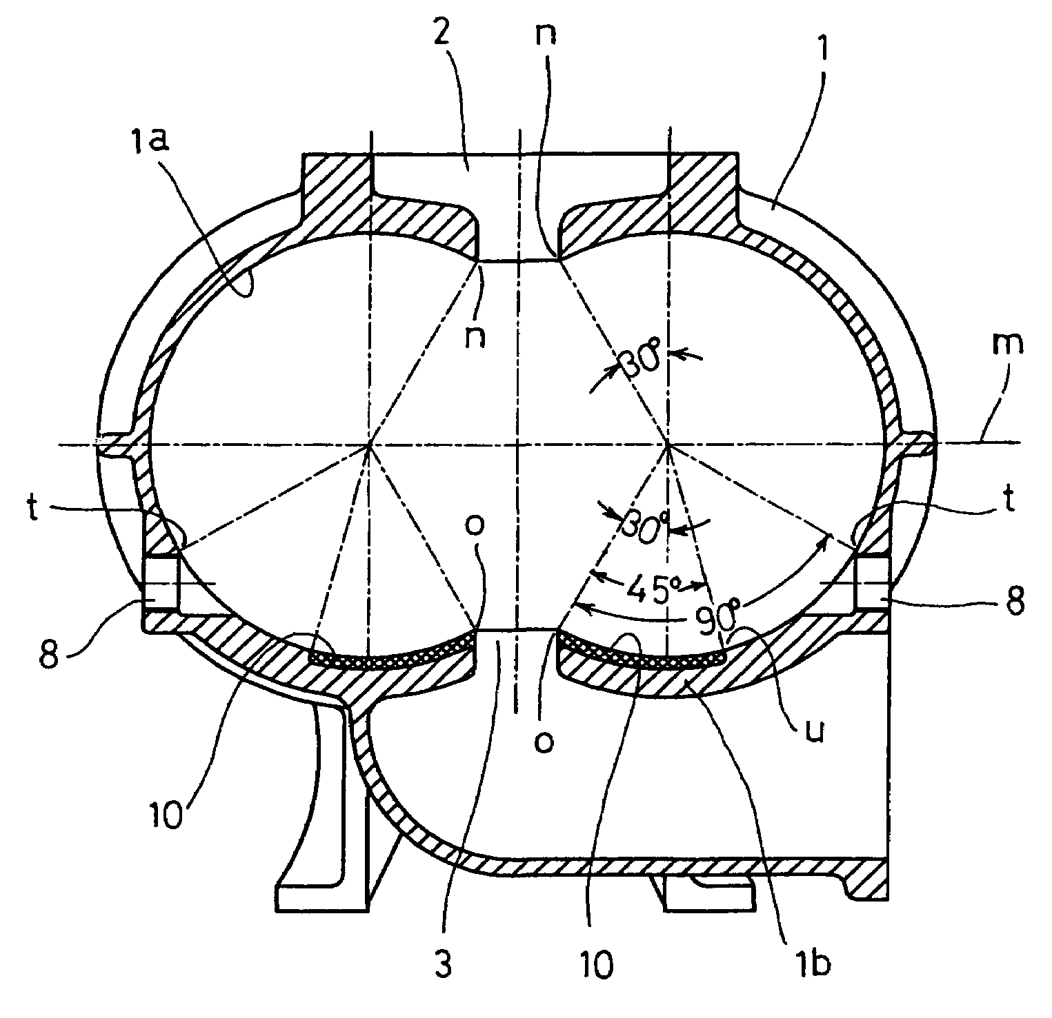
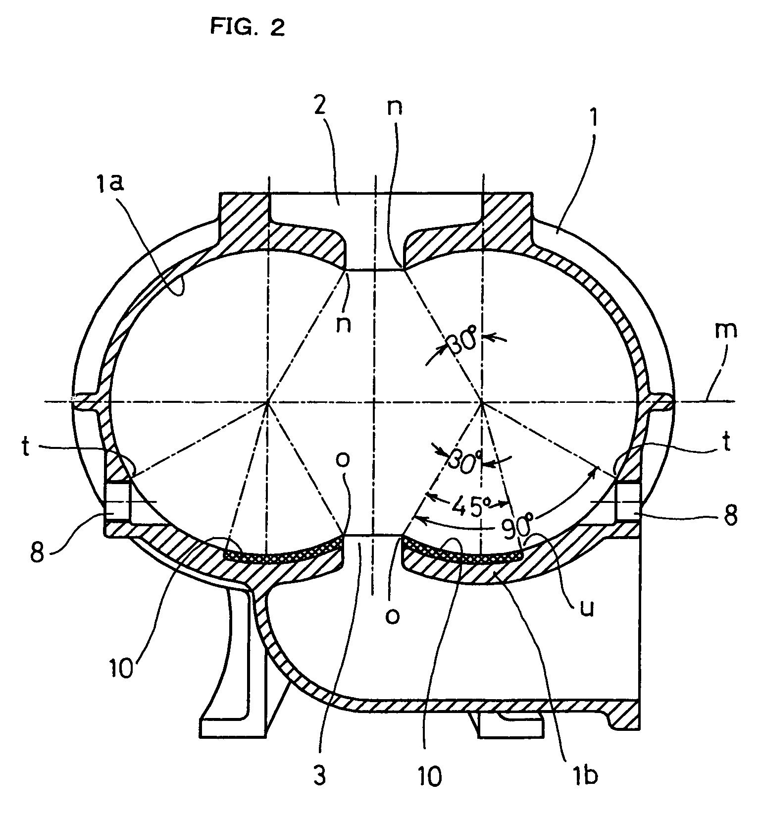
[0017]As shown in FIGS. 1 and 2, the inlet port 2 is located at a position n spaced by a positive displacement angle of 120° or above in one direction from centers of the rotating shafts 5 and 7 relative to an imaginary line m connecting the centers ...


PUM


Abstract

In a Roots vacuum pump, an inlet port is located at a position n spaced by a positive displacement angle of 120° in one direction from a center of each rotational axis relative to an imaginary line m connecting rotor axes. An outlet port is located at a position o opposite to the inlet port relative to the line. An air feed port is formed at a position t on a casing wall obtained by returning by 90° from the position o to the inlet port side so that two closed spaces are defined by adjacent rotor lobes and a casing inner wall at both port sides immediately after air suction respectively. The casing has discharge grooves in an area of the inner wall so as to communicate with the outlet port. The area ranges from the position o to a position u obtained by returning by 45° from the position o to the inlet port side. The discharge grooves have a total volume ranging from 2% to 5% of a volume of one of the closed spaces.

Description

CROSS-REFERENCE TO RELATED APPLICATIONS[0001]This application is based upon and claims the benefit of priority from the prior Japanese Patent Application No. 2006-153097, filed on Jun. 1, 2006, the entire contents of which are incorporated herein by reference.BACKGROUND OF THE INVENTION[0002]1. Field of the Invention[0003]The present invention relates to a three-lobed spar rotor or helical rotor type Roots vacuum pump used as a vacuum source for dust collectors.[0004]2. Description of the Related Art[0005]In conventional positive displacement Roots vacuum pumps, a casing at an outlet port side has a temperature ranging from about 120° C. to about 150° C. by heat of compression when pressure difference of −45 kPa or above is caused between an inlet port side and the outlet port side during operation of the pumps. Consequently, domestic and foreign manufacturers have taken necessary steps since about 1960 in order to prevent the temperature increase. In one of such steps, the casing i...

Claims


Application Information

Patent Timeline
Patent Type & Authority Patents(United States)
IPC IPC(8): F03C2/00F04C2/00
CPCF04C15/0049F04C18/126F04C18/18
Inventor YOKOI, YASUNAITO, YOSHINOBU
Owner ANLET CO LTD
Why Eureka
Try Eureka