Gas flowrate control device for gas burner

a control device and gas burner technology, applied in the field of gas burners, can solve the problems of not being able to adjust the consumer's needs, the flame may be still too weak to satisfy the user's demand, and the inconvenience of disposable gas lighters, etc., and achieve the effect of convenient adjustmen

Inactive Publication Date: 2007-06-05
TSAI CHIN LIN
View PDF5 Cites 12 Cited by
  • Summary
  • Abstract
  • Description
  • Claims
  • Application Information

AI Technical Summary

Problems solved by technology

When adjusted to the maximum status, the flame may be still too weak to satisfy the user's demand.
Most people who ever used disposable gas lighters have experienced this inconvenience.
Most consumers cannot make this adjustment, and may throw the gas lighter away.
However, the coupling structure between the wheel and the regulating component requires a high precision, thereby complicating the processing.

Method used


Image

  • Gas flowrate control device for gas burner
  • Gas flowrate control device for gas burner
  • Gas flowrate control device for gas burner

Examples


Embodiment Construction

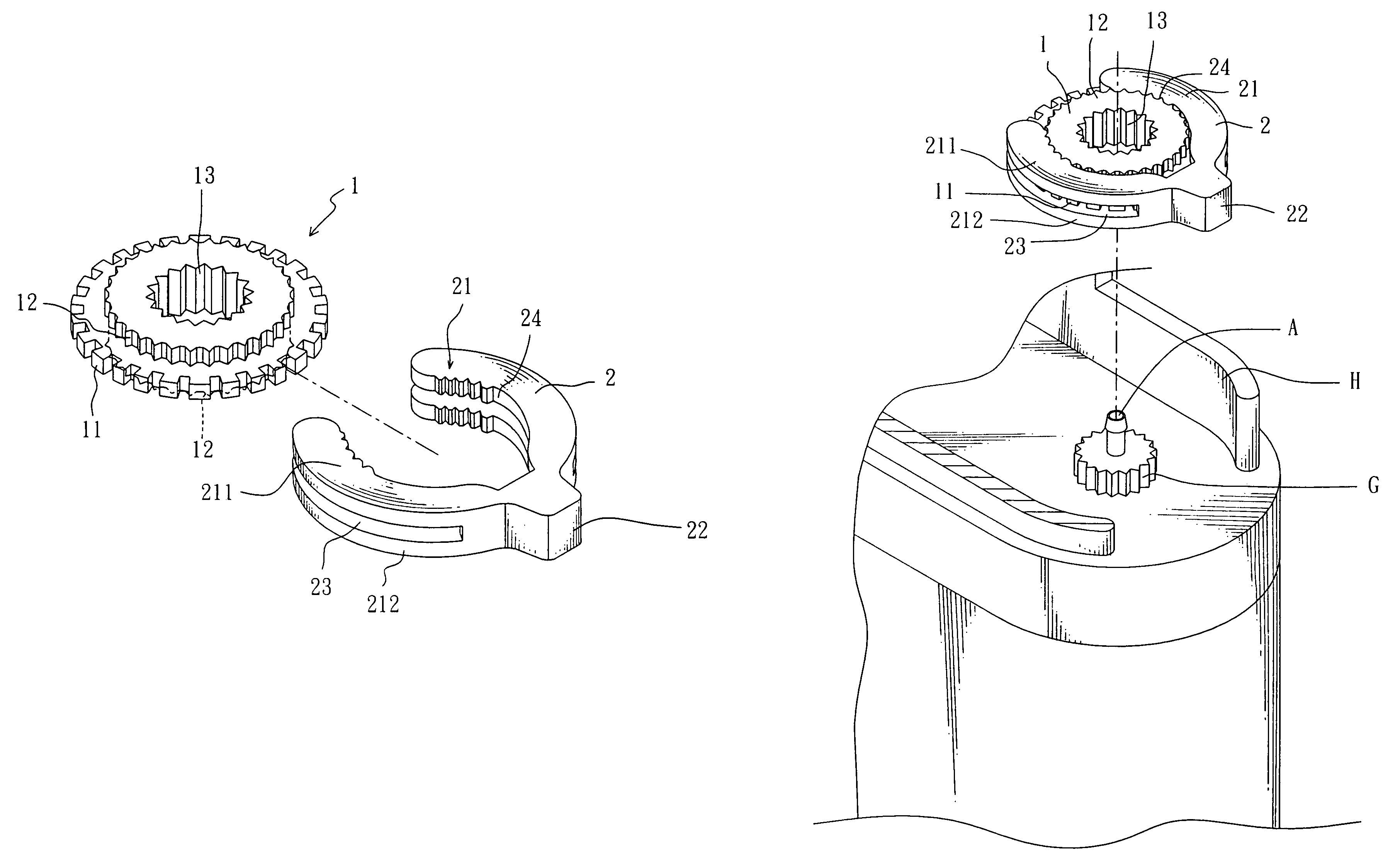
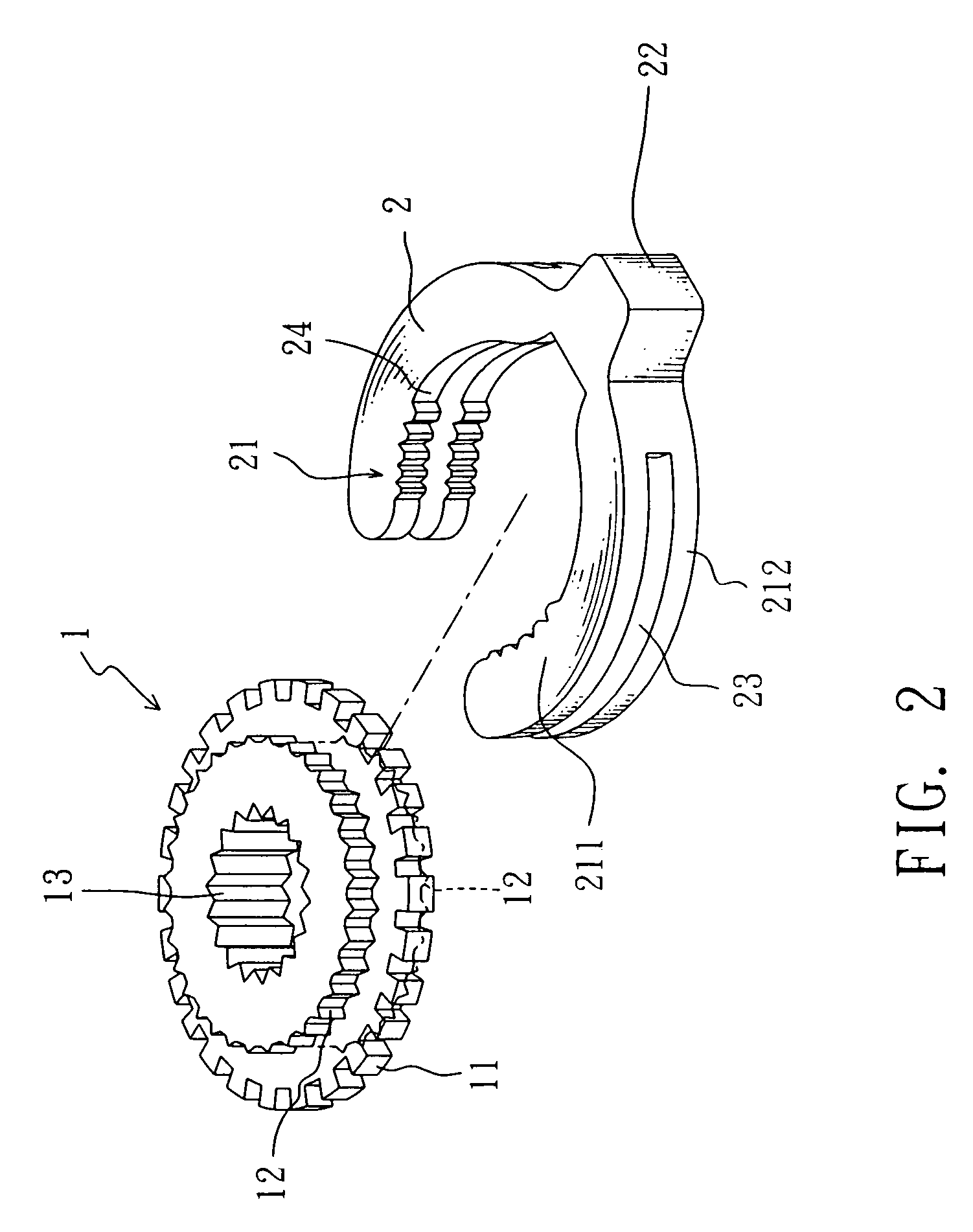
[0013]Referring to FIG. 2, a gas flowrate control device in accordance with the present invention is shown comprised of a control wheel 1 and a handle 2.

[0014]The control wheel 1 comprises an internal gear 13, a big gear 11 surrounding the internal gear 13, and two small gears 12 respectively formed integral with the two sides of the big gear 11 and surrounding the internal gear 13.

[0015]The handle 2 comprises a grip 22 and two arched clamping arms 21 symmetrically extending from the grip 22. Each arched clamping arm 21 comprises an upper arm portion 211, a lower arm portion 212, and a crevice 23 defined between the upper arm portion 211 and the lower arm portion 212. The upper arm portion 211 and the lower arm portion 212 have an equal thickness corresponding to the height of the small gears 12. Further, the upper arm portion 211 and the lower arm portion 212 each have teeth 24 provided in the end portion for engaging the small gears 12. The height of the crevice 23 is approximatel...


PUM


Abstract

A gas flowrate control device for turning the flame adjustment wheel of a gas burner is disclosed to include a control wheel, which has an internal gear meshed with the flame adjustment wheel of the gas burner, a big gear surrounding the internal gear, and two small gears respectively formed integral with two sides of the big gear and surrounding the internal gear, and a handle, which has a grip and two arched clamping arms symmetrically extending from the grip and clamped on the control wheel, each arched clamping arm having two toothed arm positions respectively meshed with the two small gears of the control wheel and a crevice defined between the two arm portions for accommodating the big gear.

Description

BACKGROUND OF THE INVENTION[0001]1. Field of the Invention[0002]The present invention relates to a gas burner and more specifically, to the gas flowrate control device for use in a gas burner for controlling the output flowrate of gas.[0003]2. Description of the Related Art[0004]Gas burners are commonly used in gas ranges, gas lighters, and etc. For regulating the output of gas, a gas lighter is equipped with a gas flowrate control device (flame adjustment wheel).[0005]FIG. 1 is an exploded view of a conventional gas lighter. As illustrated, the gas lighter comprises a gas nozzle A for output of gas, a gas valve B for controlling output of gas to the gas nozzle A, and a gas lever D for controlling the operation of the gas valve B. The gas lever D has a toothed portion E meshed with the flame adjustment wheel C of the gas valve B. According to this design, the gas lever D is movable between two opposite upright top walls F, i.e., the gas flowrate adjustment range is limited to the an...

Claims


Application Information

Patent Timeline
Patent Type & Authority Patents(United States)
IPC IPC(8): F23D11/36F16K51/00F23Q2/08
CPCF23D14/60F23Q2/173F23K2401/201F23K2900/05001F23K2400/201
Inventor TSAI, CHIN-LIN
Owner TSAI CHIN LIN
Why Eureka
Try Eureka