Chained terminals and method of forming chained terminals
a chained terminal and terminal technology, applied in the field of chained terminals, can solve the problems of increasing the width and the cost of the chained terminal, and achieve the effect of increasing the strength at each widened portion and insufficient strength
- Summary
- Abstract
- Description
- Claims
- Application Information
AI Technical Summary
Benefits of technology
Problems solved by technology
Method used
Image
Examples
first embodiment
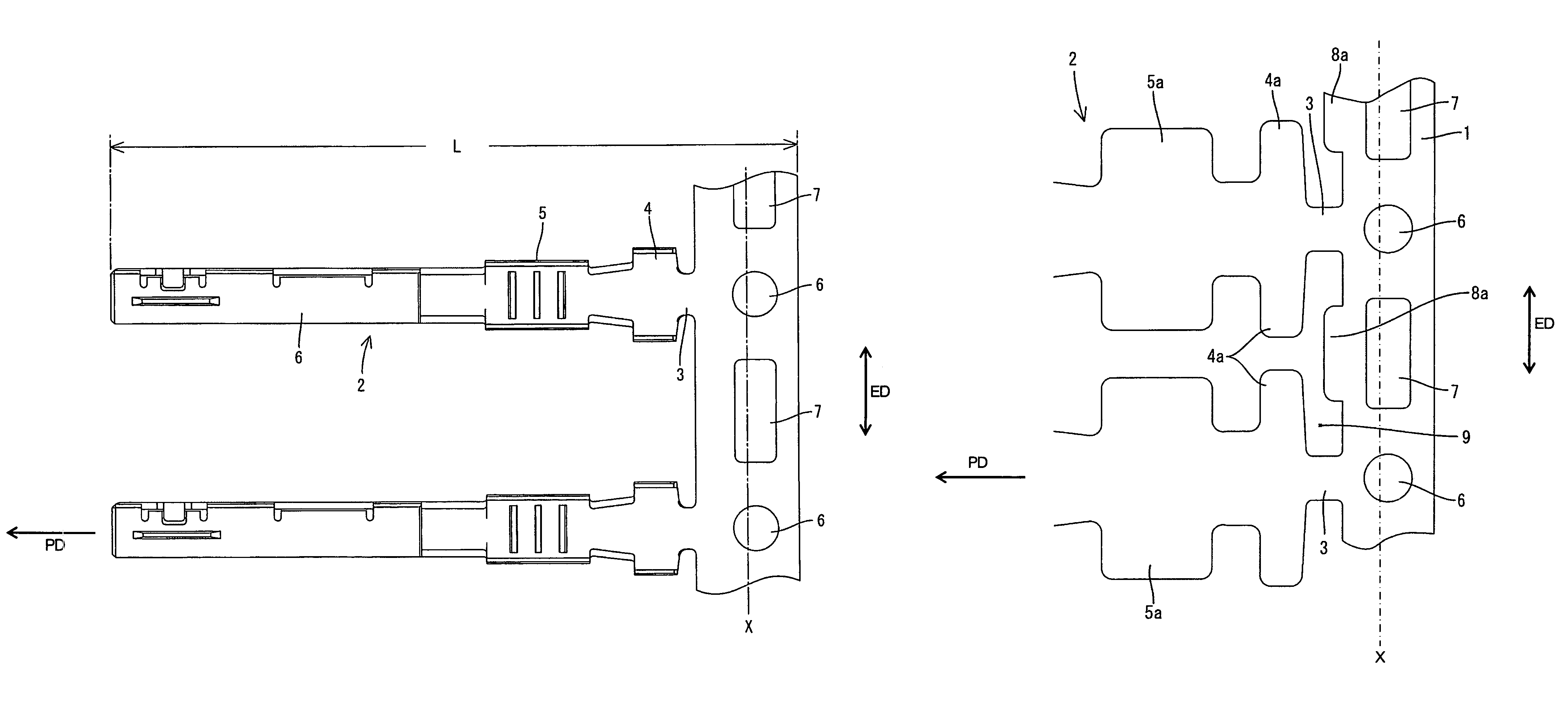
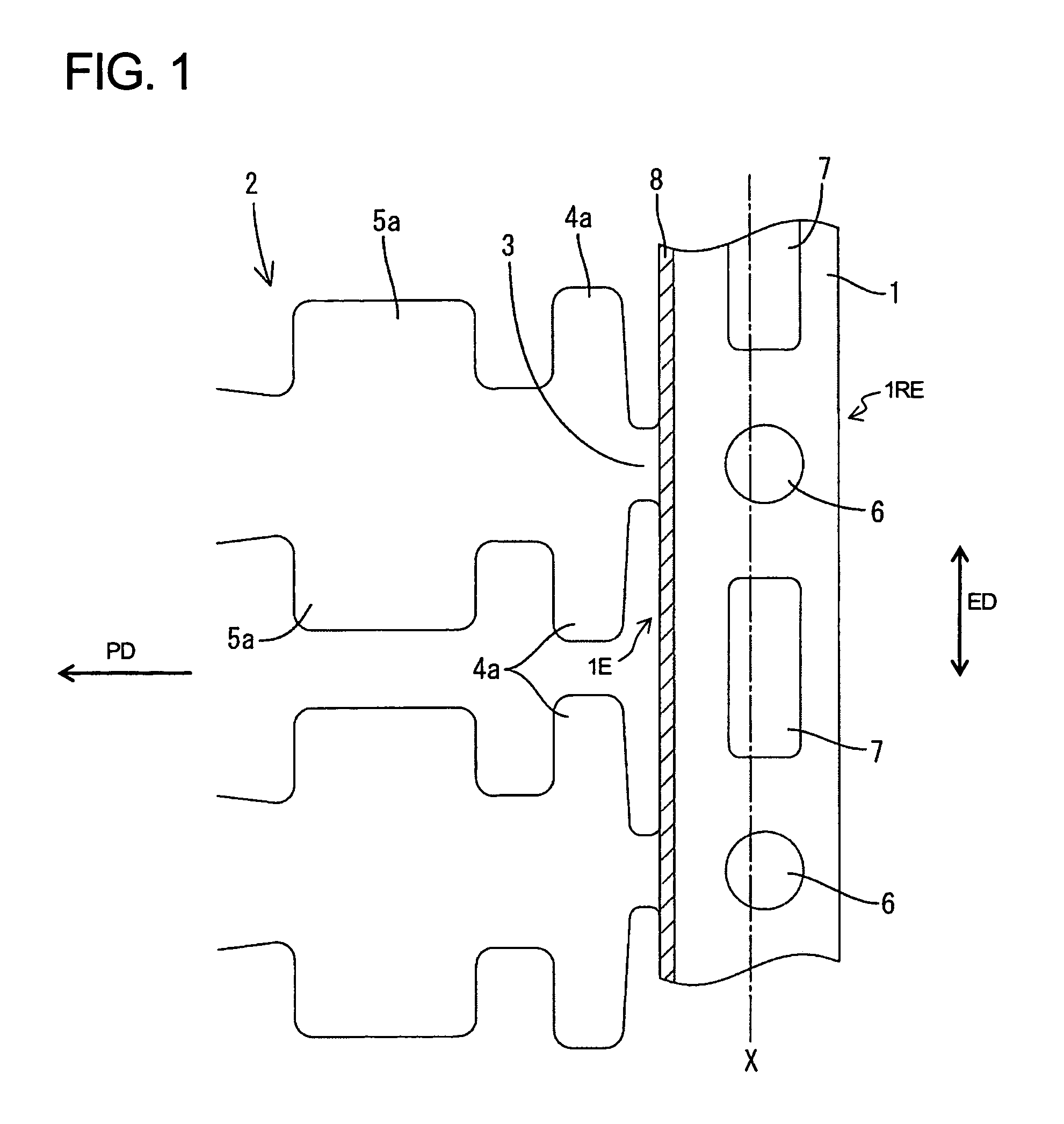
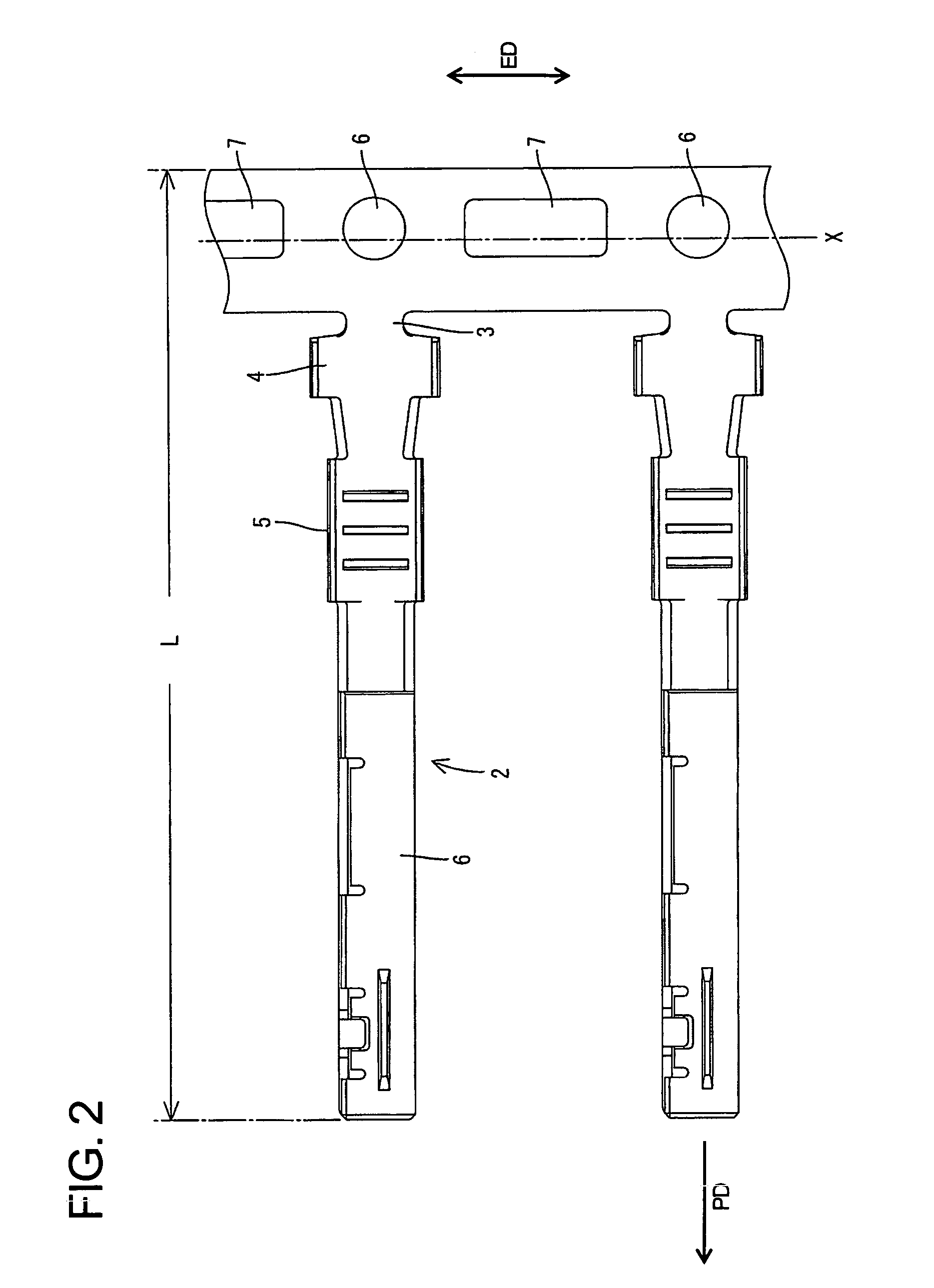
[0023]Chained terminals according to the invention are described with reference to FIGS. 1 and 2. The chained terminals are punched from an elongated metallic plate to define a blank of a specified shape, as shown in FIG. 1. The chained terminals include a carrier 1 in the form of an elongated band that extends in an extending direction ED. The carrier 1 has opposite first and second side edges 1E and 1RE. Female terminal fittings 2 cantilever or project in a projecting direction PD from the first side edge 1E of the carrier 1. The projecting direction PD of each terminal fitting 2 is substantially orthogonal to the extending direction ED of the carrier 1. The terminal fittings 2 are spaced apart at substantially even intervals along the extending direction ED. Coupling pieces 3 extend unitarily between the carrier 1 and the respective terminal fittings2. The coupling pieces 3 are located substantially on the widthwise center axes of the corresponding terminal fittings 2, as shown i...
second embodiment
[0028]The widening of the second embodiment is achieved by reinforcing tabs 8a only in a longitudinal intermediate part of each die-punched region 9 and substantially in the same length range as the second feed hole 7. Thus, an opening of a relatively large width exists between remaining parts of the carrier 1 and the narrower barrel pieces 4a, as shown in FIG. 3.
[0029]The reinforcing tabs 8a of the second embodiment are only in the part of the die-punched region 9 aligned with the second feed holes 7. Thus, a larger stronger press die can be used to form the die-punched region 9, and the carrier 1 is stronger near the second feed holes 7.
[0030]The other construction is similar to the first embodiment, and the first and second feed holes 6, 7 are deviated to the right in FIG. 3 from the widthwise center axis X of the carrier 1, including the widened portions 8a.
[0031]FIG. 4 shows a third embodiment that is similar to the second embodiment. However, the third embodiment has sloped e...
PUM
| Property | Measurement | Unit |
|---|---|---|
| distances | aaaaa | aaaaa |
| speed | aaaaa | aaaaa |
| length | aaaaa | aaaaa |
Abstract
Description
Claims
Application Information
 - R&D
- Intellectual Property
- Life Sciences
- Materials
- Tech Scout
- Unparalleled Data Quality
- Higher Quality Content
- 60% Fewer Hallucinations
Browse by: Latest US Patents, China's latest patents, Technical Efficacy Thesaurus, Application Domain, Technology Topic, Popular Technical Reports.
© 2025 PatSnap. All rights reserved.Legal|Privacy policy|Modern Slavery Act Transparency Statement|Sitemap|About US| Contact US: help@patsnap.com


