Fanless building ventilator

a ventilator and fanless technology, applied in ventilation systems, heating types, separation processes, etc., can solve problems such as the effect of affecting the air quality of the building, the health of the occupant, and the illness of the building, so as to reduce the operating cost, and reduce the effect of nois

Inactive Publication Date: 2007-06-05
RANCO OF DELAWARE
View PDF100 Cites 32 Cited by
  • Summary
  • Abstract
  • Description
  • Claims
  • Application Information

AI Technical Summary

Benefits of technology

[0007]The invention provides a new and improved heat recovery ventilator (HRV) and a new and improved energy recovery ventilator (ERV). More particularly, the invention provides a new and improved HRV and a new and improved ERV that replaces the traditional fan technologies with corona-based air movement technology to exchange indoor / outdoor air. The benefits provided by this technology are: quieter operation, a more compact device, lower operating cost, and trapping contaminants from the incoming air (such as mold and pollen).

Problems solved by technology

While this is beneficial from a natural resource perspective, it has a potentially negative impact on the air quality within the building.
Consequently this can lead to sick building syndrome, and problems for allergy suffering occupants.
However, such HRVs and ERVs require the use of blower fans to move the air through the system.
Unfortunately, these blower fans generate noise, utilize rotating parts, require a larger housing, have a high operating cost, and cannot act to filter the air that they move.

Method used


Image

  • Fanless building ventilator
  • Fanless building ventilator
  • Fanless building ventilator

Examples


Embodiment Construction

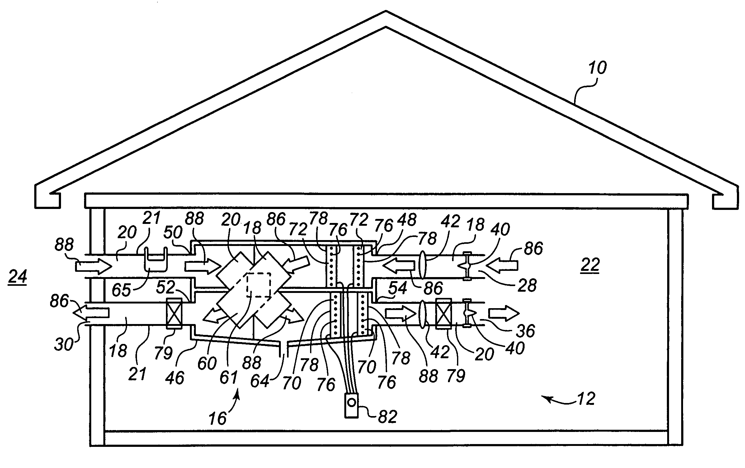
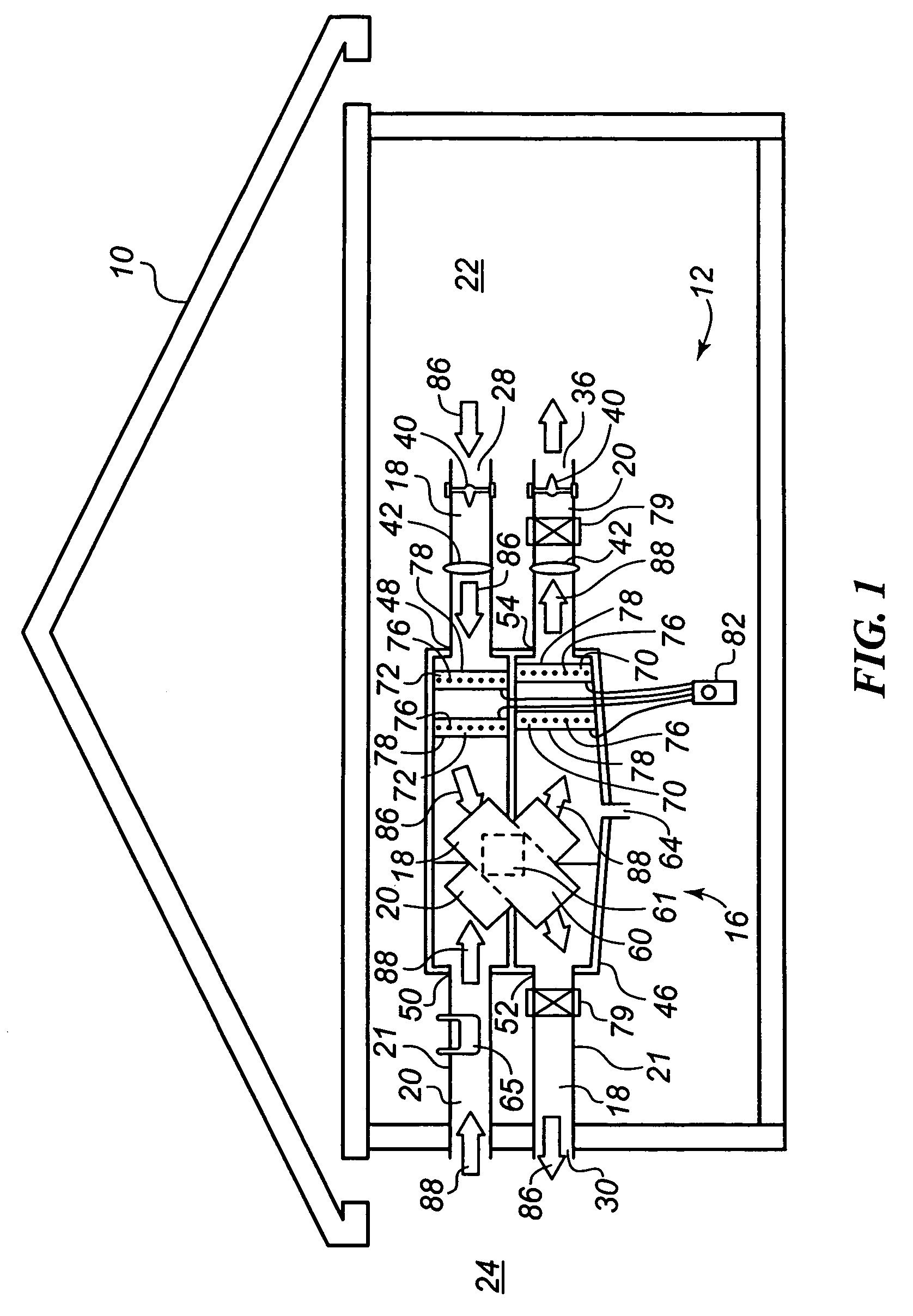
[0015]Referring to FIG. 1, a building 10 having a ventilation system 12 constructed in accordance with the present invention is illustrated. As will be described more fully below, the ventilation system 12 is constructed to quietly and efficiently move a fluid (e.g. air) into and out of the building 10 without using moving parts.

[0016]As shown, the preferred ventilation system 12 generally comprises a heat recovery ventilator and / or an energy recovery ventilator (hereinafter referred to generally as an HRV / ERV unit 16), a stale air passage 18 and a fresh air passage 20. It will be appreciated that all ventilation systems do not require an HRV / ERV unit.

[0017]The stale air passage 18 and the fresh air passage 20 are relatively similar in that they both provide a passage defined by a network of interconnected sealed ducts 21 that connect the interior 22 of the building 10 with the exterior 24 of the building 10 such that the interior 22 and exterior are in controlled fluid communicatio...


PUM


Abstract

A ventilation system for a building is provided. The ventilation system includes a pair of passages between the interior and exterior of the building and at least one corona discharge apparatus for drawing fluid through the passages. The ventilation system may also include an energy recovery ventilator for transferring energy, humidity or the combination of energy and humidity between the fluid flowing through the two passages. Variable flow rates through the passages are provided by varying the voltage to the corona discharge apparatus. In addition, the corona discharge apparatuses may filter the air flowing through the passages.

Description

CROSS-REFERENCE TO RELATED PATENT APPLICATIONS[0001]This patent application claims the benefit of U.S. Provisional Patent Application No. 60 / 632,320, filed Nov. 30, 2004, the teachings and disclosure of which are hereby incorporated in their entireties by reference thereto.FIELD OF THE INVENTION[0002]This invention pertains to building ventilator systems, and more particularly to heat recovery ventilators (HRVs) and energy recovery ventilators (ERVs) used to improve indoor air quality.BACKGROUND OF THE INVENTION[0003]In newly constructed buildings, modern energy-saving building materials are extensively utilized. While this is beneficial from a natural resource perspective, it has a potentially negative impact on the air quality within the building. The well-insulated and sealed building that keeps outside ambient air outside, and conditioned air inside, also prevents pollutants from escaping. Consequently this can lead to sick building syndrome, and problems for allergy suffering o...

Claims


Application Information

Patent Timeline
Patent Type & Authority Patents(United States)
IPC IPC(8): B03C3/155
CPCB01D53/32B03C3/011B03C3/017B03C3/32B03C2201/14
Inventor ASHWORTH, NICHOLAS
Owner RANCO OF DELAWARE
Why Eureka
Try Eureka