Plural conduit replaceable outer support structure for radial flow system

a technology of radial flow and conduit, which is applied in the direction of separation process, physical/chemical process catalyst, dispersed particle separation, etc., can solve the problems of non-uniform thickness of annular bed, high cost of additional materials, and inconvenient installation, etc., to achieve uniform bed thickness, easy removal, and simple installation

Inactive Publication Date: 2007-06-05
JOHNSON SCREENS
View PDF12 Cites 55 Cited by
  • Summary
  • Abstract
  • Description
  • Claims
  • Application Information

AI Technical Summary

Benefits of technology

[0007]It is among the objects of the present invention to provide an outer support structure for the particulate bed in a radial flow system which is relatively simple to install initially or when replacement is necessary by making it in individual segments which are sized so that each segment can easily be removed and can pass through a relatively small inlet opening in an end of the vessel. It is another object to provide such an outer support structure which is strong and capable of transferring outward loading applied to it by the particulate bed directly to the walls of the vessel without being deformed. It is yet another object to provide such a structure which will provide a uniform bed thickness. It is a still further object to provide such a structure in which each individual segment has a large cross-sectional area for flow to allow low flow velocities for the fluid and less turbulence. Yet another object is to provide a support structure which allows the vessel diameter to be reduced for a given thickness of particulate bed as compared to a vessel incorporating scallops. These and other objects are achieved by the mounting system of the present invention wherein a plurality of vertically extending flow conduits having an open end for receiving or distributing flow are positioned adjacent each other in a ring around the inner circumference of the outer wall of the vessel. The inner walls of the conduits comprise a screen surface which defines the outer support structure for the particulate bed and includes flow openings which are of a lesser width than the diameter of the particulate material. The screen surface is preferably formed of parallel, closely spaced wires which are welded to underlying support rods. The screens which form the inner walls are preferably flat or slightly concave so that the particulate bed which extends between them and a circular center pipe screen member will have a substantially constant radial thickness. At least some of the flow conduits have a generally trapezoidal shape. The flow conduits have an outer wall which lays against the inside vessel wall and has a radius that is the same as that of the inside vessel wall. Generally radially extending side wall portions of the conduits have such angles and clearance between adjacent conduits that any individual conduit can be moved inwardly with no more than a small sliding displacement of adjacent conduits or by removal of a maximum of one adjacent conduit.

Problems solved by technology

Although the convex surface of the scallops which supports the particulate bed is quite strong, the convex shape causes the thickness of the annular bed to be non-uniform.
Thus, the flow distribution through the bed is non-uniform and more flow will take place at the location on the scallops where their convex surface is closest to the center pipe and the pressure drop is lowest.
Where the particulate material is one which contains a precious metal such as platinum, the need for additional material can be very expensive.
In addition, the tendency for flow to take place where the flow distance is at its shortest results in uneven contact between the fluid to be reacted and the particulate material in the bed.
This uneven flow can result in the need to replace the particulate material sooner than if the flow was entirely uniform.
However, the systems is quite expensive since the large diameter screen cannot be installed or removed through a small upper opening in the vessel, as can the scallops type screen.

Method used


Image

  • Plural conduit replaceable outer support structure for radial flow system
  • Plural conduit replaceable outer support structure for radial flow system
  • Plural conduit replaceable outer support structure for radial flow system

Examples


Embodiment Construction

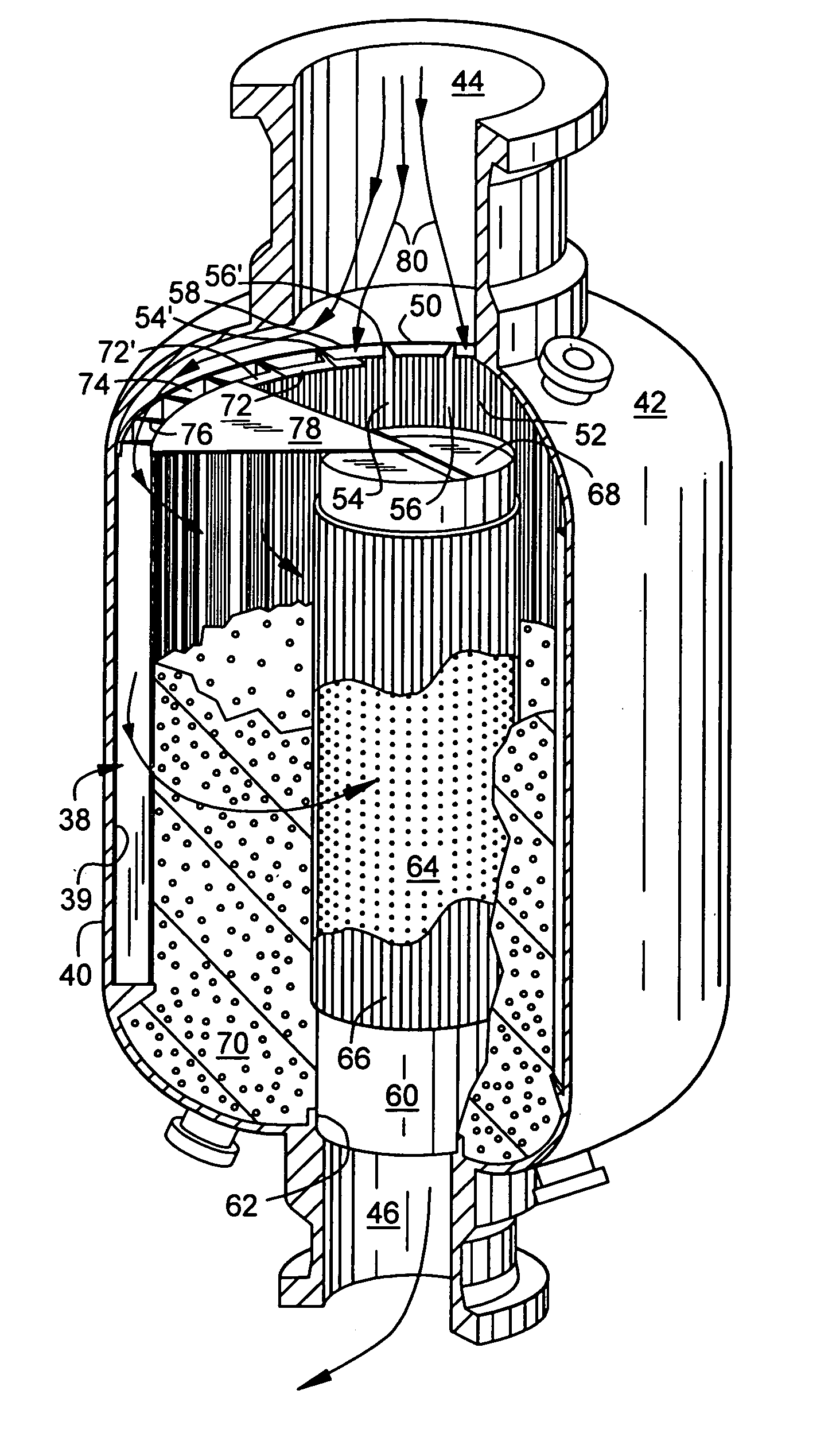
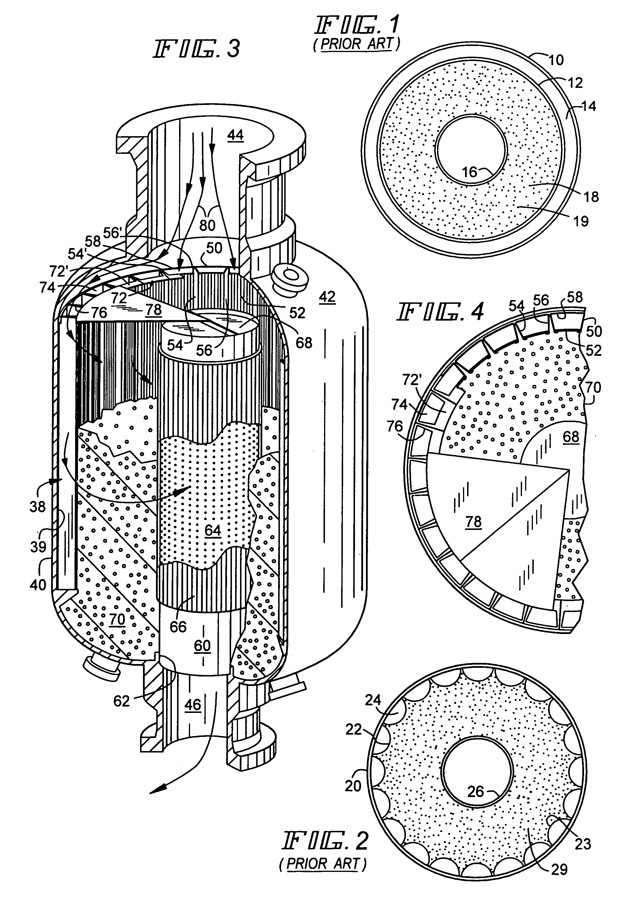
[0018]FIG. 1 is a cross-sectional view similar to FIG. 2 and FIG. 4 which illustrates one type of construction used for a prior art radial flow reactor vessel (not shown). A vertical, generally cylindrical outer wall member 10 cooperates with a cylindrical outer screen basket member 12 to define an outer annular opening 14. The screen basket member 12 is concentrically located relative to a center mounted vertical screen pipe 16 to define the outer and inner walls of an inner annulus area 18 which is packed with an annular bed of particulate material 19 such as a catalyst. In normal use, the fluid to be processed enters an inlet opening (not shown) at the top of the vessel and passes into the outer annular opening 14. The fluid then passes radially inwardly through openings (not shown) in the screen basket 12, through the annular bed of particulate material 19, through openings (not shown) formed in the center mounted screen pipe 16 and then moves downwardly through the screen pipe ...


PUM

PropertyMeasurementUnit
diameteraaaaaaaaaa
diameteraaaaaaaaaa
diameteraaaaaaaaaa

Abstract

Replaceable outer support structure 38 for a particulate material bed 70 in a radial flow system comprises a plurality of hollow conduits 50, 250, 260, at least some of which have a generally trapezoidal cross-section. The conduits are arranged in a ring around the inside wall surface 39 of the vessel 42 and have flat or slightly concave inner wall surfaces 52 formed of segments of vertically extending screen members which have slots or openings 86 which provide uniform flow through the uniform thickness particulate bed which they help define The side walls 54, 56 of the conduits extend generally radially outwardly to engage the inner surface 39 of the outside wall 40 of the vessel and at least those of them which have a trapezoidal cross-section have their side walls formed at an included angle α which is less than if they extended radially relative to the axis of the vessel. An embodiment having alternating generally trapezoidal 250 and generally rectangular cross-sections 260 for the conduit members maximizes the total internal flow area of the ring of conduits as compared to an embodiment in which all of the conduit members have a trapezoidal shape, while still allowing the inward movement of individual conduit members during installation or replacement operations.

Description

BACKGROUND OF THE INVENTION[0001]1) Field of the Invention[0002]The invention relates to the fluid conduits which form the outer retaining wall for an annular particulate bed used in a radial flow system mounted in a cylindrical vessel. In such systems a fluid typically is directed radially inwardly or outwardly into or out of the particulate bed through openings in the inner surfaces of a plurality of outer, vertically arranged conduit members or through openings in a cylindrical screen basket member which has a smaller diameter than the inner wall of the vessel. The fluid passes through openings in a vertically arranged center pipe which forms the inner retaining wall for the annular particulate bed.[0003]2) Description of the Related Art[0004]The vessel typically is a reactor which contains a bed of particulate material such as catalyst, absorbent, resins or activated carbon. The fluid which passes through the particulate bed in a radial direction is usually a gas but it could al...

Claims


Application Information

Patent Timeline
Patent Type & Authority Patents(United States)
IPC IPC(8): B01J8/02B01D53/04B01J8/00
CPCB01D53/0431B01D53/0446B01J8/0085B01J8/0214B01J8/0278B01J2208/00884B01J2219/185B01J2219/1943
Inventor HAM, PIERRE M.BLANCHON, ALAIN M.LAVERNHE, PHILIPPE O.NADERI, HOSSEIN A.
Owner JOHNSON SCREENS
Why Eureka
Try Eureka