Fuel containment and recycling system

a technology of fuel containment and recycling system, which is applied in the direction of cell components, secondary cell maintenance/maintenance, maintenance/service of primary cells, etc., can solve the problems of wasting space, major obstacle to providing a commercially viable system, and system never achieved commercial success, etc., to achieve convenient, economical and environmentally friendly effects

Inactive Publication Date: 2007-06-05
REVEO
View PDF90 Cites 23 Cited by
  • Summary
  • Abstract
  • Description
  • Claims
  • Application Information

AI Technical Summary

Benefits of technology

[0009]In view of the above, it is an object of the present invention to provide a convenient, economical and environmentally safe fuel supply and waste material retrieval system for use with an energy conversion device.
[0013]It is yet another object of the present invention to eliminate short-circuiting between a plurality of electrochemical cells having a single fuel feed.

Problems solved by technology

Since oxygen is readily available in the air, it is usually unnecessary to utilize a dedicated oxygen storage vessel for the fuel-cell battery (except in certain configurations where there the oxygen supply is limited due to design considerations).
These systems never achieved any commercial success because they all had relatively low power output (acceptable drain rates and overall capacities).
Until now, this has been the major obstacle to providing a commercially viable system.
While this arrangement increases the drain rate by removing the reaction materials, the multiple reservoir design wastes space, adds complexity, and increases cost.
Although effective for the pellet-type fuel particles disclosed in the patent, this expedient cannot block the passage of the small anode particles that are found in a paste-like fuel substance.

Method used


Image

  • Fuel containment and recycling system
  • Fuel containment and recycling system
  • Fuel containment and recycling system

Examples


Embodiment Construction

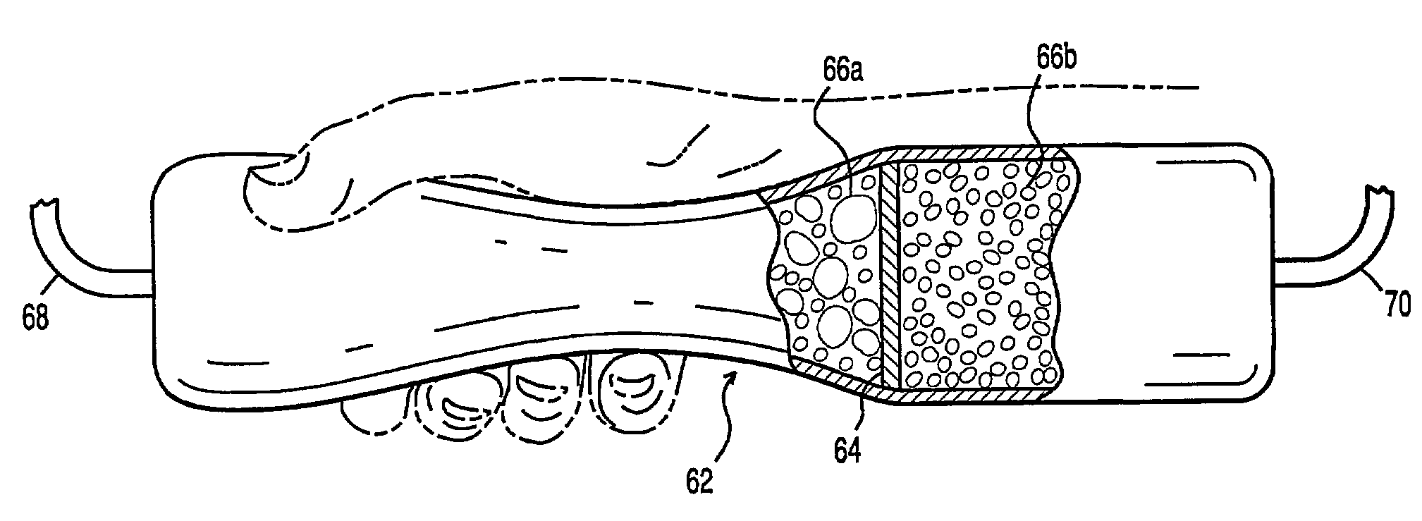
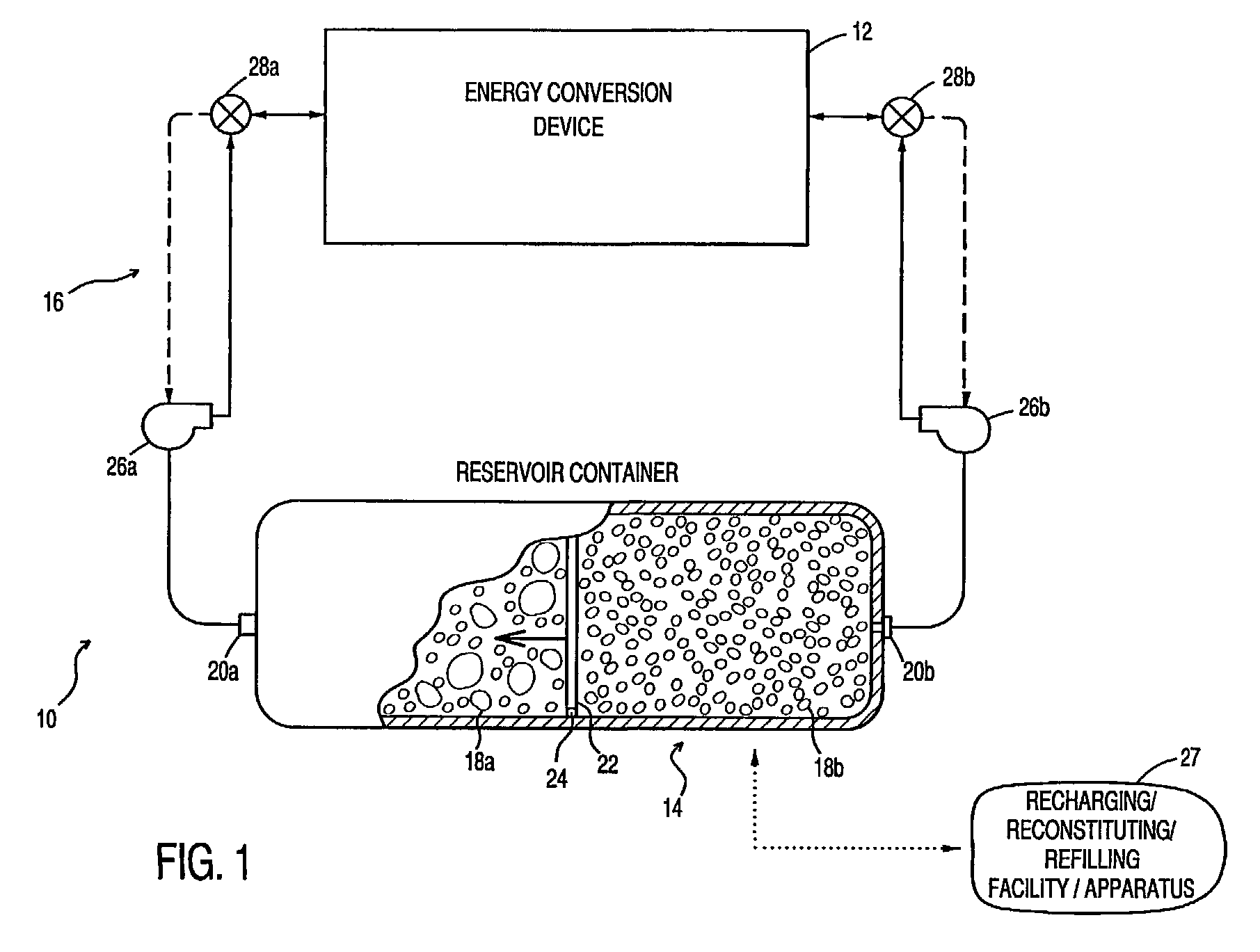
[0039]The low energy density of typical metal air batteries has prevented their practical use in high rate applications such as, for example, powering motor vehicles. The present invention overcomes the shortcomings in the prior art by using a single reservoir container to dispense the fuel and to collecting and reconsituting the electrochemical reactants (i.e., mostly metal oxide) in a manner similar to secondary battery systems. The hybrid configuration (i.e., refuelable / rechargeable) provides a long discharge life (or high energy density), faster recharging capability leading to enhanced performance during discharge, and a longer cycle life.

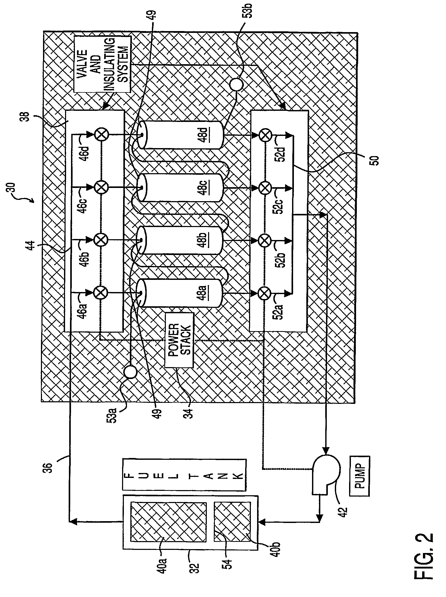
[0040]The present invention embodies “fuel splitting” wherein multiple metal / air cell voltages are obtained with only one fuel source without short-circuiting the cells. As a result, batteries made with the cell configuration of the present invention can provide at least about 330 Wh / kg / 750 Wh / L, making them well suited as a power source for p...


PUM

PropertyMeasurementUnit
discharging current densityaaaaaaaaaa
sizesaaaaaaaaaa
sizesaaaaaaaaaa

Abstract

An energy conversion system, comprising: a reservoir container including at least two chambers of inversely variable volume for respectively storing a quantity of fuel and receiving a quantity of exhaust; a means for decreasing the volume of the first chamber while concurrently increasing the volume of the second chamber; at least one energy conversion device; first means for communicating fuel between the at least one energy conversion device and a first of the chambers in the reservoir container; and second means for communicating exhaust between the at least one energy conversion device and a second of the chambers in the reservoir container. The reservoir container may be transported to a recharging / refilling station or recharged in-situ. A particular application for metal-air fuel cell power systems is shown and described.

Description

RELATED APPLICATIONS[0001]The present application is a Continuation Application and claims priority under 35 USC 120 of application Ser. No. 09 / 570,798 filed on May 12, 2000, to issue on May 6, 2003 as U.S. Pat. No. 6,558,825.FIELD OF THE INVENTION[0002]The present invention relates generally to fuel and exhaust containment for energy conversion systems, and more particularly, to fuel containers and recycling systems for metal-air fuel cells.BACKGROUND OF THE INVENTION[0003]Fuel cells, and in particular metal-air battery systems, have long been considered a desirable power source in view of their inherent high energy density. A fuel-cell battery includes a cathode, an ionic medium and an anode. A metal-air cell employs an anode comprised of metal particles that is fed into the cell and oxidized as the cell discharges. The cathode is generally comprised of a semipermeable membrane, a mesh of inert conductor, and a catalyzed layer for reducing oxygen that diffuses through the membrane...

Claims


Application Information

Patent Timeline
Patent Type & Authority Patents(United States)
IPC IPC(8): H01M8/04H01M2/00H01M2/02H01M4/86H01M6/50H01M8/06H01M8/10H01M8/18H01M8/22H01M10/42H01M12/06H01M50/77
CPCH01M6/5011H01M6/5077H01M8/225H01M10/4214H01M12/06H01M2/40H01M4/02Y02E60/50H01M2300/0014H01M8/18Y02E60/10H01M50/77
Inventor FARIS, SADEG M.TSAI, TSEPINYAO, WENBINCHANG, YUEN-MING
Owner REVEO
Why Eureka
Try Eureka