Fixed network resistor
a technology of fixed network resistor and resistor shell, which is applied in the direction of resistor details, resistor housing/enclosement/embedding, resistor details, etc., can solve the problems of reducing the strength of these areas, and affecting the quality of the final produ
- Summary
- Abstract
- Description
- Claims
- Application Information
AI Technical Summary
Benefits of technology
Problems solved by technology
Method used
Image
Examples
first embodiment
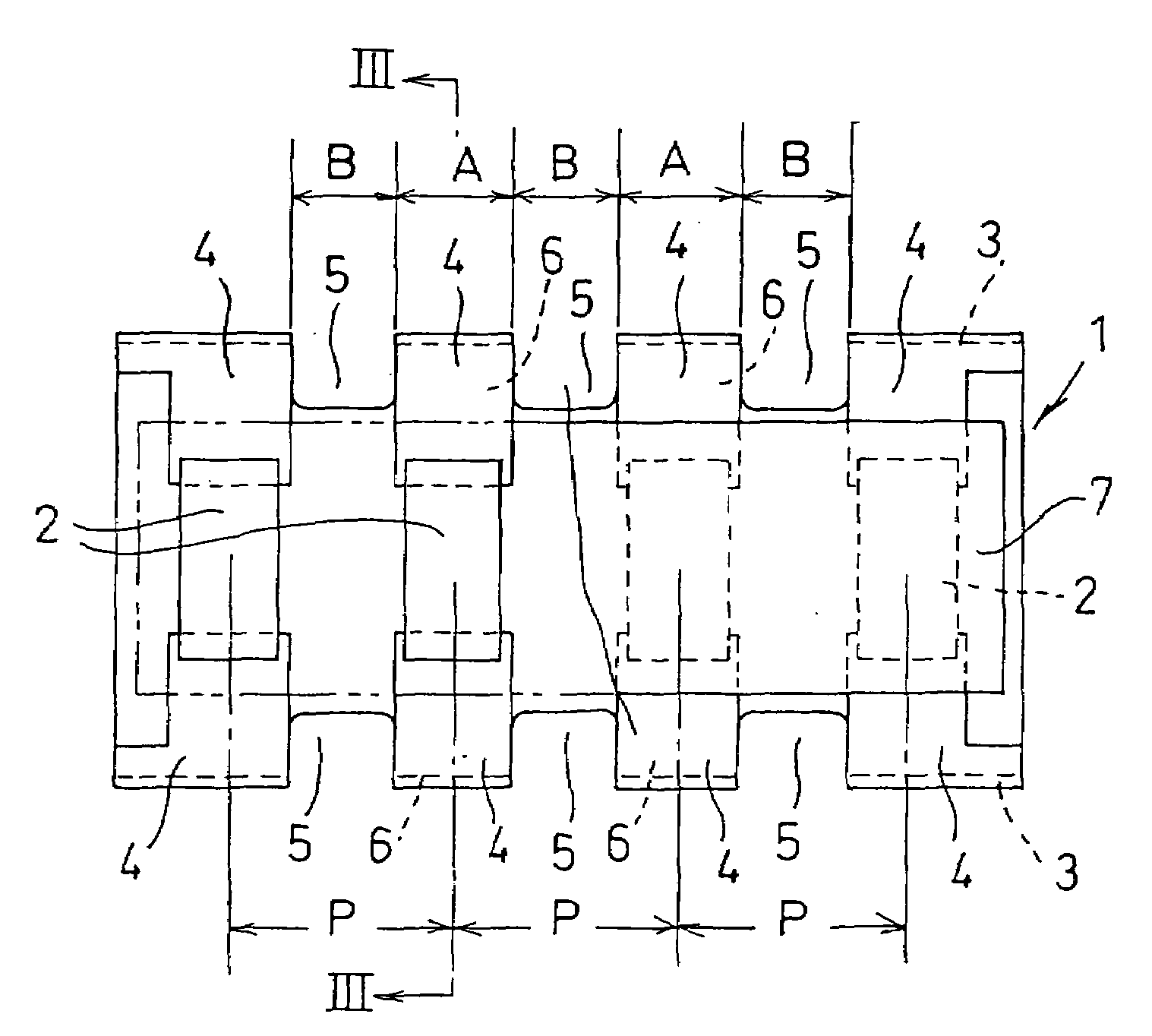
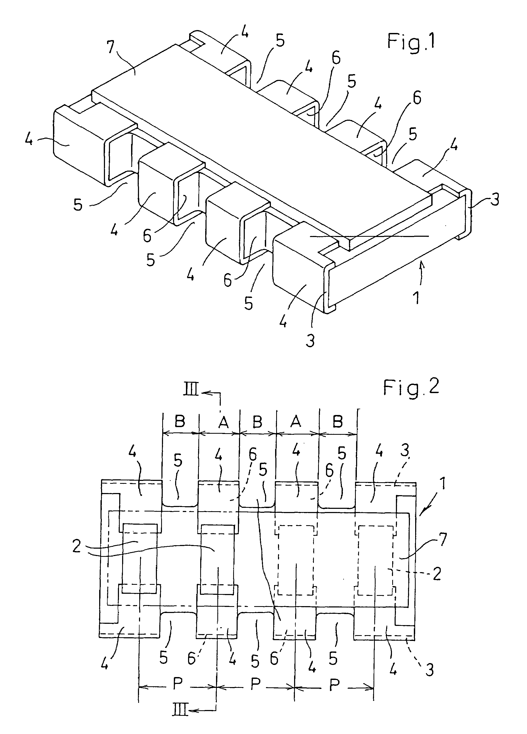
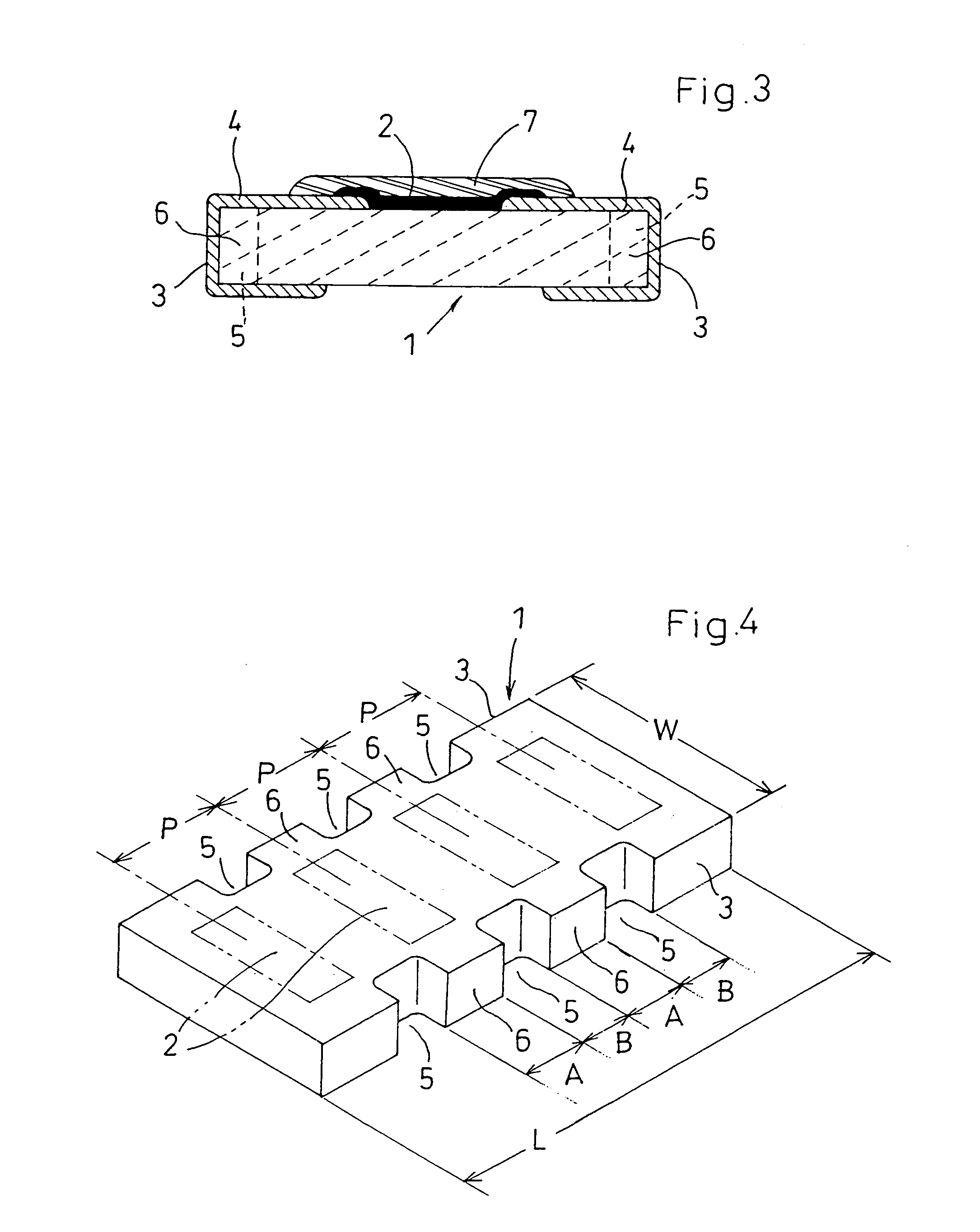
[0039]FIGS. 1 to 4 show the invention.
[0040]In these diagrams, the symbol 1 represents a ceramic insulating substrate having, in a plan view, a rectangular shape with a length L of 2.0 mm and a width W of 1.0 mm. This insulating substrate 1 has formed, on a top surface thereof, four film resistors 2 which are arranged in the lengthwise direction of the insulating substrate 1.
[0041]Terminal electrodes 4 which are electrically connected to both ends of each film resistor 2 are formed on both longitudinal sidewalls 3 of the insulating substrate 1 at a pitch P=0.5 mm along the longitudinal sidewalls 3. Recesses 5 are provided in areas between the individual terminal electrodes 4 on both of the lengthwise sidewalls 3 of the insulating substrate 1.
[0042]Each terminal electrode 4 is formed so as to extend to a bottom surface of the insulating substrate 1. On the top surface of the insulating substrate 1, a cover coat 7 made of a material such as glass is formed so as to cover each film res...
second embodiment
[0047]Next, FIGS. 5 and 6 show the invention.
[0048]This second embodiment is a three-element fixed resistor network composed of a single insulating substrate 11, of rectangular shape in a plan view, on which three film resistors 12 are arranged. Terminal electrodes 14 for both ends of the individual film resistors 12 are formed on both lengthwise sidewalls 13 of the insulating substrate 11 at a pitch P=0.5 mm along the lengthwise sidewalls 3, and recesses 15 are provided between the terminal electrodes 14. In addition, a cover coat 17 is formed on a top surface of the insulating substrate 11.
[0049]In this embodiment as well, by setting the terminal-electrode-forming areas 16 between the recesses 15 to a width A along the lengthwise sidewalls 13 such that A=(0.52 to 0.56)×P and setting the recesses 15 to a width B along the lengthwise sidewalls 13 such that B=(0.48 to 0.44)×P, defects such as the chipping or breaking off of material in the terminal-electrode-forming areas 16 can be r...
fifth embodiment
[0058]FIGS. 9 to 11 show the invention.
[0059]This embodiment is a four-element fixed resistor network in which the pitch P between the terminal electrodes was set at 0.4 mm.
[0060]In these diagrams, the symbol 41 represents a ceramic insulating substrate having, in a plan view, a rectangular shape with a length L of 1.39 mm and a width W of 0.6 mm. This insulating substrate 41 has formed, on a top surface thereof, four film resistors 42 so as to be arranged in the lengthwise direction of the insulating substrate 41.
[0061]Terminal electrodes 44 that are electrically connected to both ends of the film resistors 42 are formed, on lengthwise sidewalls 43 at both edges of the insulating substrate 41, at a pitch P=0.4 mm along the lengthwise direction of the insulating substrate 41.
[0062]Recesses 45 having a width B along the lengthwise sidewall 43 and a suitable depth C from the lengthwise sidewall 43 are provided in areas between the terminal electrodes 44 on the lengthwise sidewalls 43 ...
PUM
 Abstract
Description
Claims
Application Information
 - R&D
- Intellectual Property
- Life Sciences
- Materials
- Tech Scout
- Unparalleled Data Quality
- Higher Quality Content
- 60% Fewer Hallucinations
Browse by: Latest US Patents, China's latest patents, Technical Efficacy Thesaurus, Application Domain, Technology Topic, Popular Technical Reports.
© 2025 PatSnap. All rights reserved.Legal|Privacy policy|Modern Slavery Act Transparency Statement|Sitemap|About US| Contact US: help@patsnap.com


