
Transport channel multiplexing system and method

Inactive Publication Date: 2007-06-05
LUCENT TECH INC
View PDF4 Cites 71 Cited by
  • Summary
  • Abstract
  • Description
  • Claims
  • Application Information

AI Technical Summary

Benefits of technology

[0008]The present invention is a transport channel multiplexing system which provides improved use of wireless resources in a shared data channel system. For example, the transport channel system reduces the amount of transport format information required for using a shared data channel, such as the actual number of packet data units in a transport channel of the shared data channel. Additionally, by scheduling or multiplexing coded sub-blocks from one or more transport channels over the shared data channel, the transport channel multiplexing system can provide improved integration with other important features, such as incremental redundancy, fast adaptation to channel conditions and transport channel dependent quality of service (QOS) control, to provide improved system performance.

Problems solved by technology

Due to the delay-intolerant nature of voice communication, wireless units in conventional cellular systems transmit and receive over dedicated links between a wireless unit and a base station.
As such, using dedicated links to transmit data is an inefficient use of network resources.

Method used


Image

  • Transport channel multiplexing system and method
  • Transport channel multiplexing system and method

Examples


Embodiment Construction

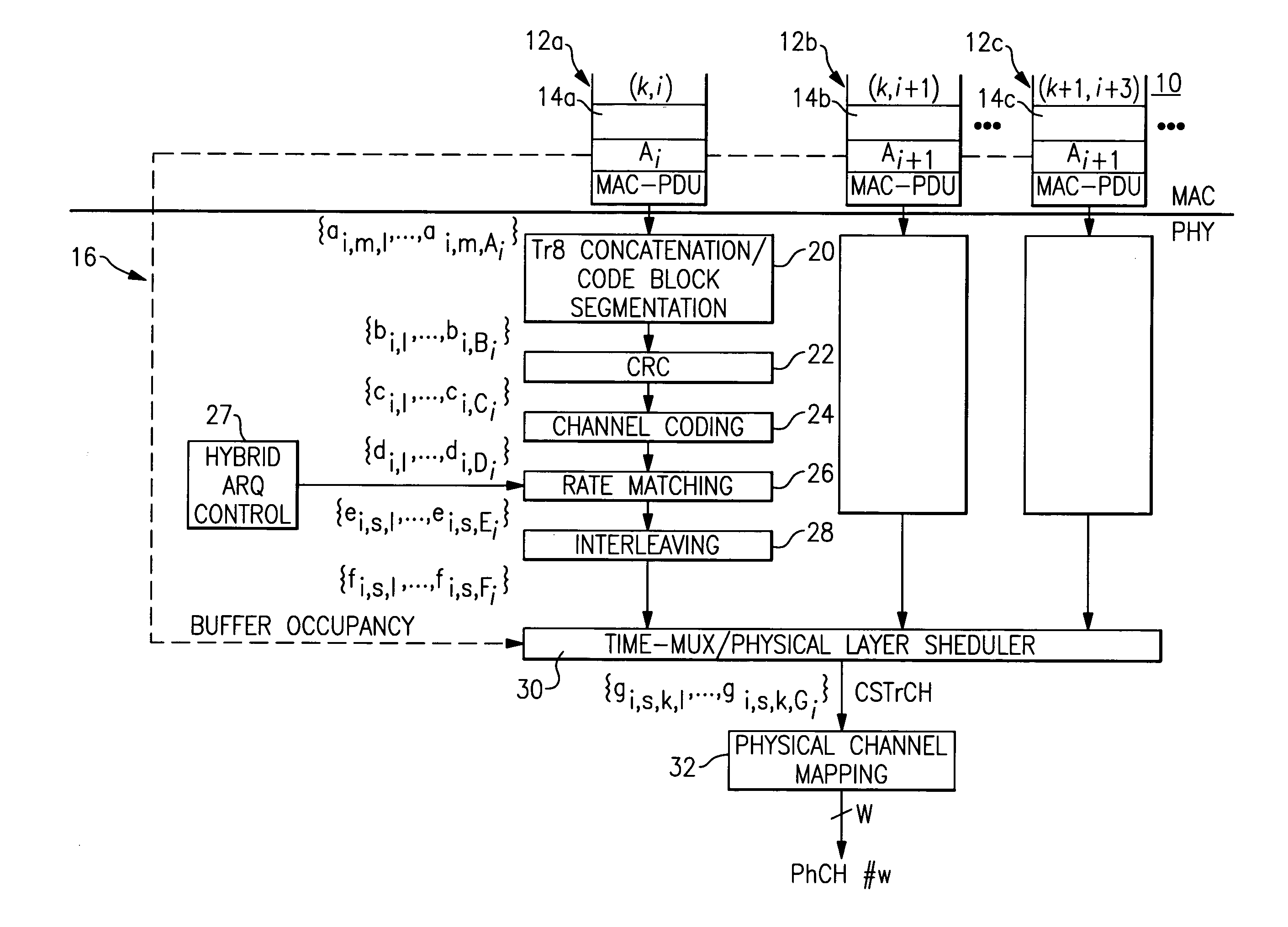
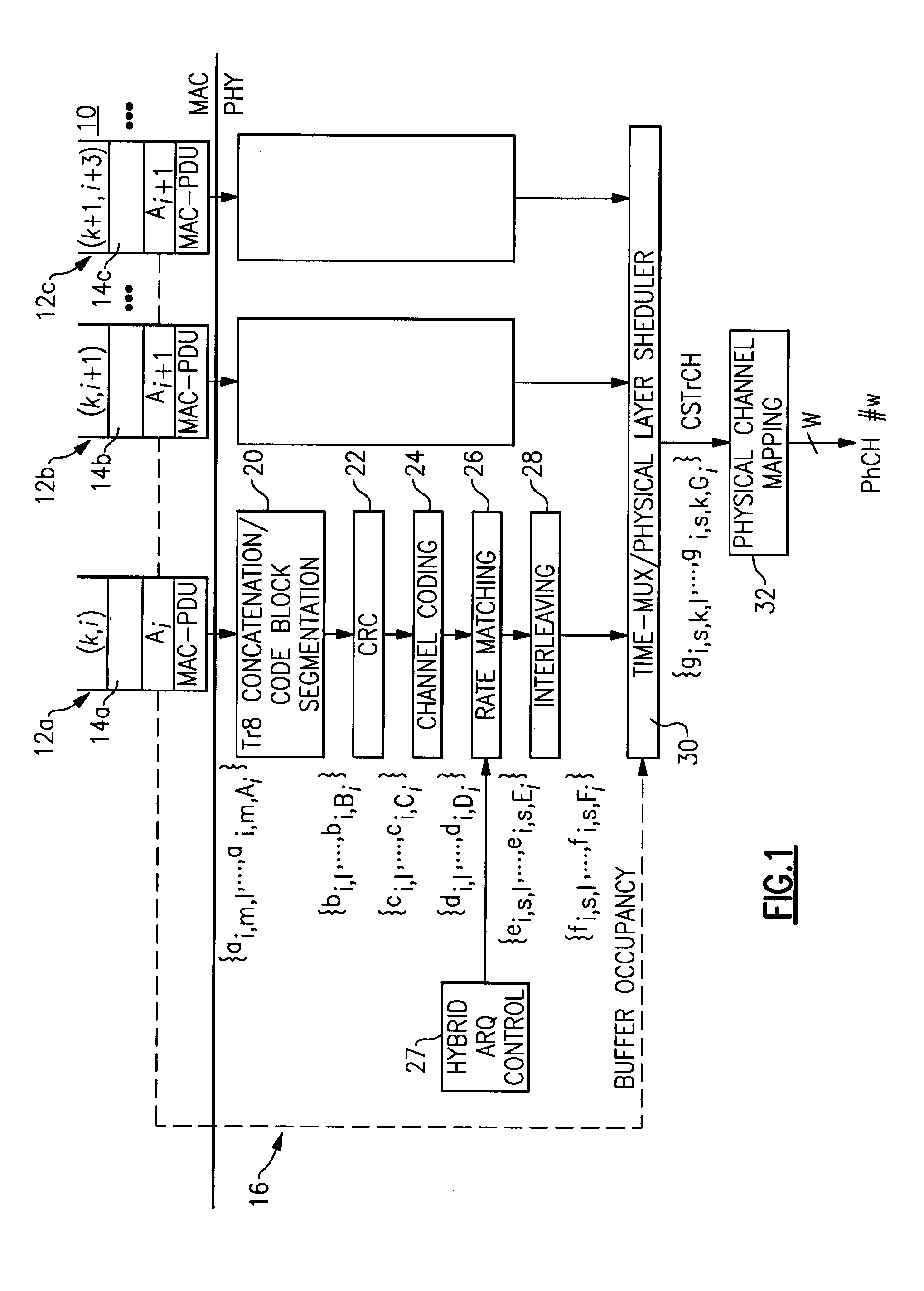
[0011]Illustrative embodiments of the transport channel multiplexing system are described with respect to a system using a downlink shared channel for packet data communications. For example, a UMTS system has a downlink shared channel which is defined by at least one and more likely a plurality of channelization codes. The downlink shared channel is time division multiplexed, being divided into 10 millisecond frames of 15 slots of 0.667 milliseconds. In certain embodiments, the wireless units provide rate and antenna feedback from which the base station decides whether to provide the wireless unit with packet data access to the downlink shared channel. The downlink shared channel is comprised of a number of transport channels, and the transport channel multiplex structure maps or multiplexes the transport channel onto a Coded Shared Transport Channel which in turn is multiplexed or mapped into a physical downlink shared channel for transmission to the wireless units.

[0012]The trans...


PUM


Abstract

A transport channel multiplexing system provides improved use of wireless resources in a shared data channel system. For example, the transport channel system reduces the amount of transport format information required for using a shared data channel, such as the actual number of packet data units in a transport channel of the shared data channel. Additionally, by scheduling or multiplexing coded sub-blocks from one or more transport channels over the shared data channel, the transport channel multiplexing system can provide improved integration with other important features, such as incremental redundancy, fast adaptation to channel conditions and transport channel dependent quality of service (QOS) control, to provide improved system performance.

Description

BACKGROUND OF THE INVENTION[0001]1. Field of the Invention[0002]This invention relates to wireless communications and, more particularly, to a transport channel multiplexing system that supports a downlink shared channel system.[0003]2. Description of Related Art[0004]Wireless communications systems include conventional cellular communication systems which comprise a number of cell sites or base stations, geographically distributed to support transmission and receipt of communication signals to and from wireless units which may actually be stationary or fixed. Each cell site handles voice communications over a particular region called a cell, and the overall coverage area for the cellular communication system is defined by the union of cells for all of the cell sites, where the coverage areas for nearby cell sites overlap to some degree to ensure (if possible) contiguous communications coverage within the outer boundaries of the system's coverage area.[0005]When active, a wireless u...

Claims


Application Information

Patent Timeline
IPC IPC(8): H04B7/216H04L1/00H04L1/18
CPCH04L1/0025H04L1/0029H04L1/0068H04L1/0071H04L1/0079H04L1/1819H04L1/1874H04L1/1887
Inventor GOPALAKRISHNAN, NANDUHU, TECK H.KHAN, FAROOQ ULLAHKOGIANTIS, ACHILLES GEORGEMONOGIOUDIS, PANTELISSAMPATH, ASHWIN
Owner LUCENT TECH INC
Features
  • Generate Ideas
  • Intellectual Property
  • Life Sciences
  • Materials
  • Tech Scout
  • Unparalleled Data Quality
  • Higher Quality Content
  • 60% Fewer Hallucinations
Learn More