

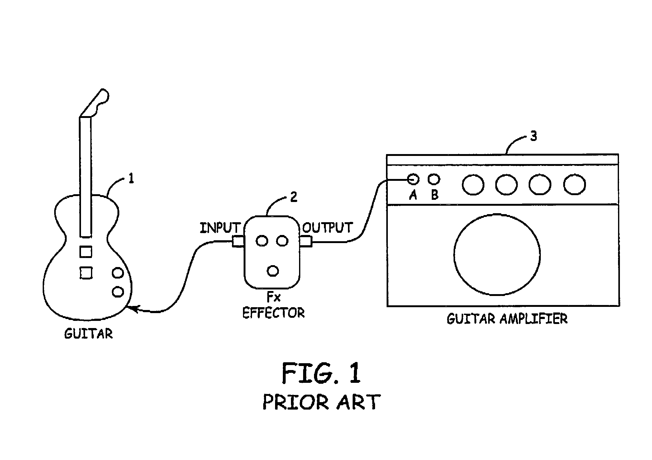
One-terminal effector
a technology of effector and terminal, applied in the field of effector, can solve the problems of sound quality, complex cable wiring, use of a plurality of cables, etc., and achieve the effect of reducing constraints and preventing degradation of sound quality
- Summary
- Abstract
- Description
- Claims
- Application Information
AI Technical Summary
Benefits of technology
Problems solved by technology
Method used
Image

Examples
Embodiment Construction
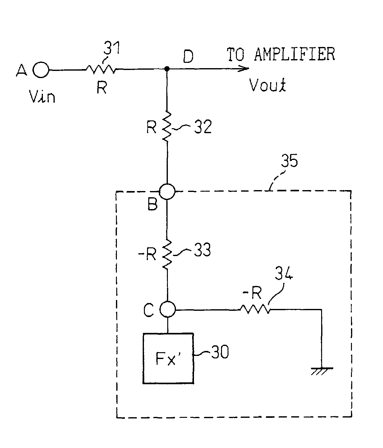
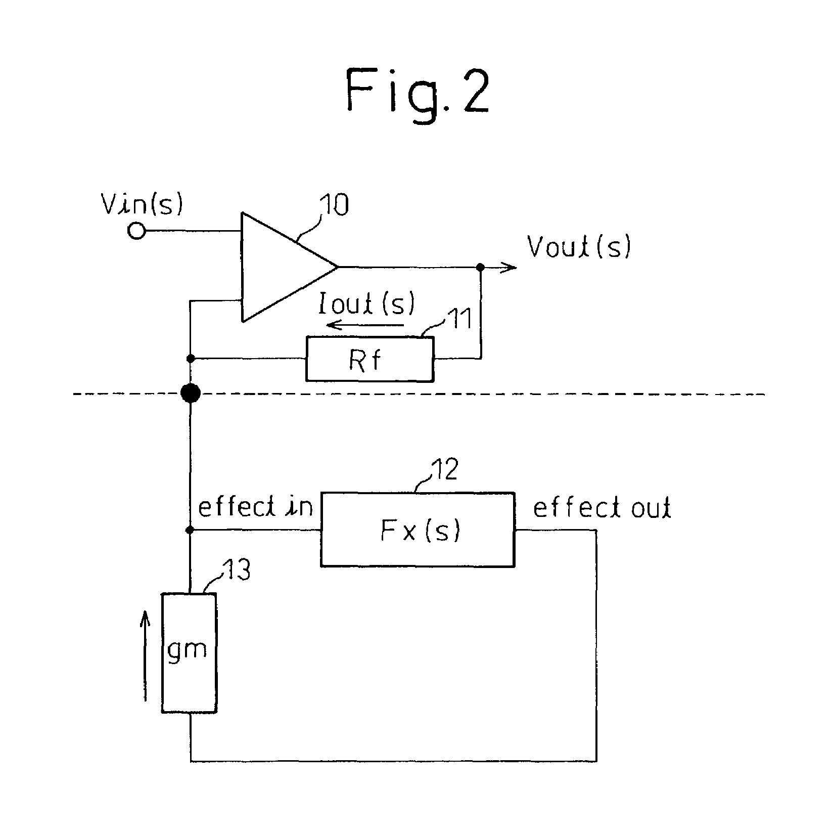
[0038]FIG. 2 is a diagram showing a first principle structure of a one-terminal effector according to the present invention. In FIG. 2, a portion above a dotted line at the center of the drawing corresponds to the guitar amplifier 3 shown in FIG. 1, and a portion below the dotted line corresponds to a one-terminal effector according to the present invention. A white circle in the drawing corresponds to an input terminal A of the guitar amplifier 3, and a black circle in the drawing corresponds to an input terminal B of the guitar amplifier 3. Vout(s) represents an input signal to an amplifier circuit inside the guitar amplifier 3. The one-terminal effector side is constructed of an effector section (Fx(s)) 12 and a mutual conductance (gm) 13.
[0039]FIGS. 3A and 3B show one example of a circuit structure of the effector section 12 and the mutual conductance 13 shown in FIG. 2, respectively.
[0040]FIG. 3A shows an example of the effector section 12 structured by a digital signal process...
PUM
 Abstract
Description
Claims
Application Information