Path planner and method for planning a path plan having a spiral component

a path planner and spiral component technology, applied in the direction of process and machine control, distance measurement, instruments, etc., can solve the problem that the execution of the path plan may consume more energy than desired

Inactive Publication Date: 2007-06-05
DEERE & CO
View PDF33 Cites 70 Cited by
  • Summary
  • Abstract
  • Description
  • Claims
  • Application Information

AI Technical Summary

Problems solved by technology

If the path plan is limited to linear rows, the execution of the path plan may consume more energy than desired to traverse sloped terrain or to cover a given work area in an energy efficient manner.

Method used


Image

  • Path planner and method for planning a path plan having a spiral component
  • Path planner and method for planning a path plan having a spiral component
  • Path planner and method for planning a path plan having a spiral component

Examples


Embodiment Construction

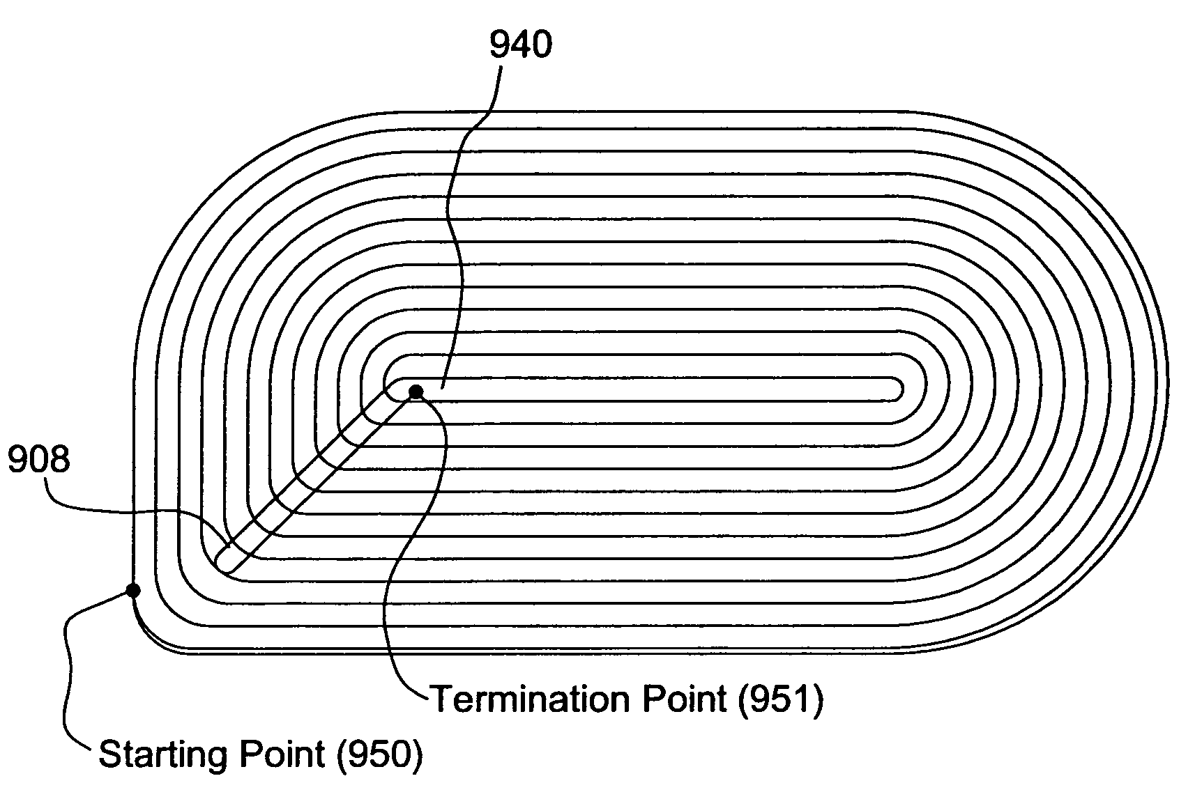
[0022]A spiral component means any of the following: (1) a path plan or contour rows that follows a generally spiral path, (2) a path plan or contour rows that comprises a series of nested loops (e.g., concentric paths or concentric path rings) that are interconnected to one another, (3) a path plan or contour rows having a continuous curve of variable radius that begins from an outer border and works inward, and (4) a path plan or contour rows having a continuous curve of variable radius from an inner border and works outward.

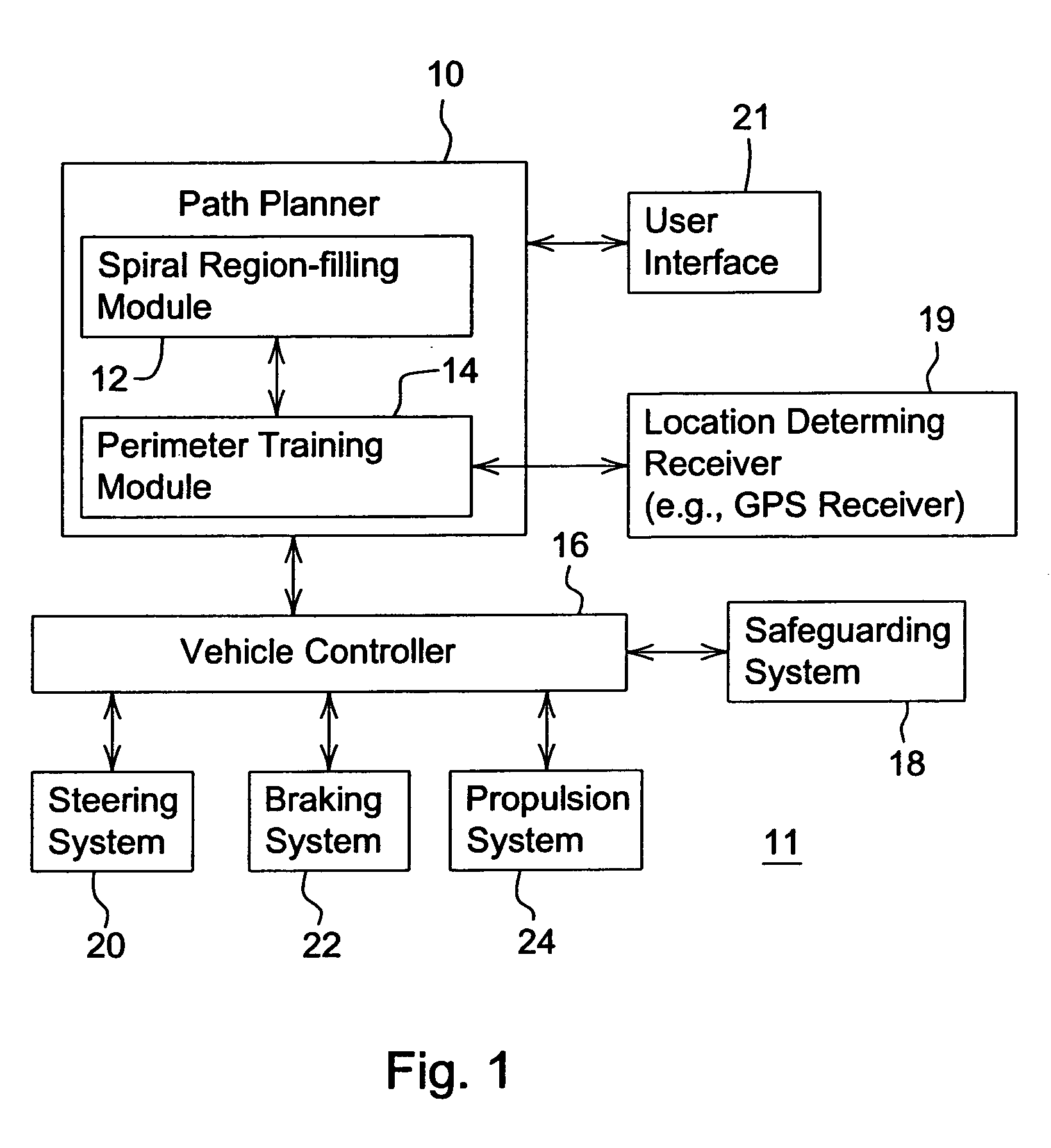
[0023]In FIG. 1, the path planning system 11 comprises a path planner 10 that is coupled to a user interface 21, a location-determining receiver 19, and a vehicle controller 16. In turn, the vehicle controller 16 may communicate with one or more of the following components: a steering system 20, a braking system 22, a propulsion system 24, and a safeguarding system 18.

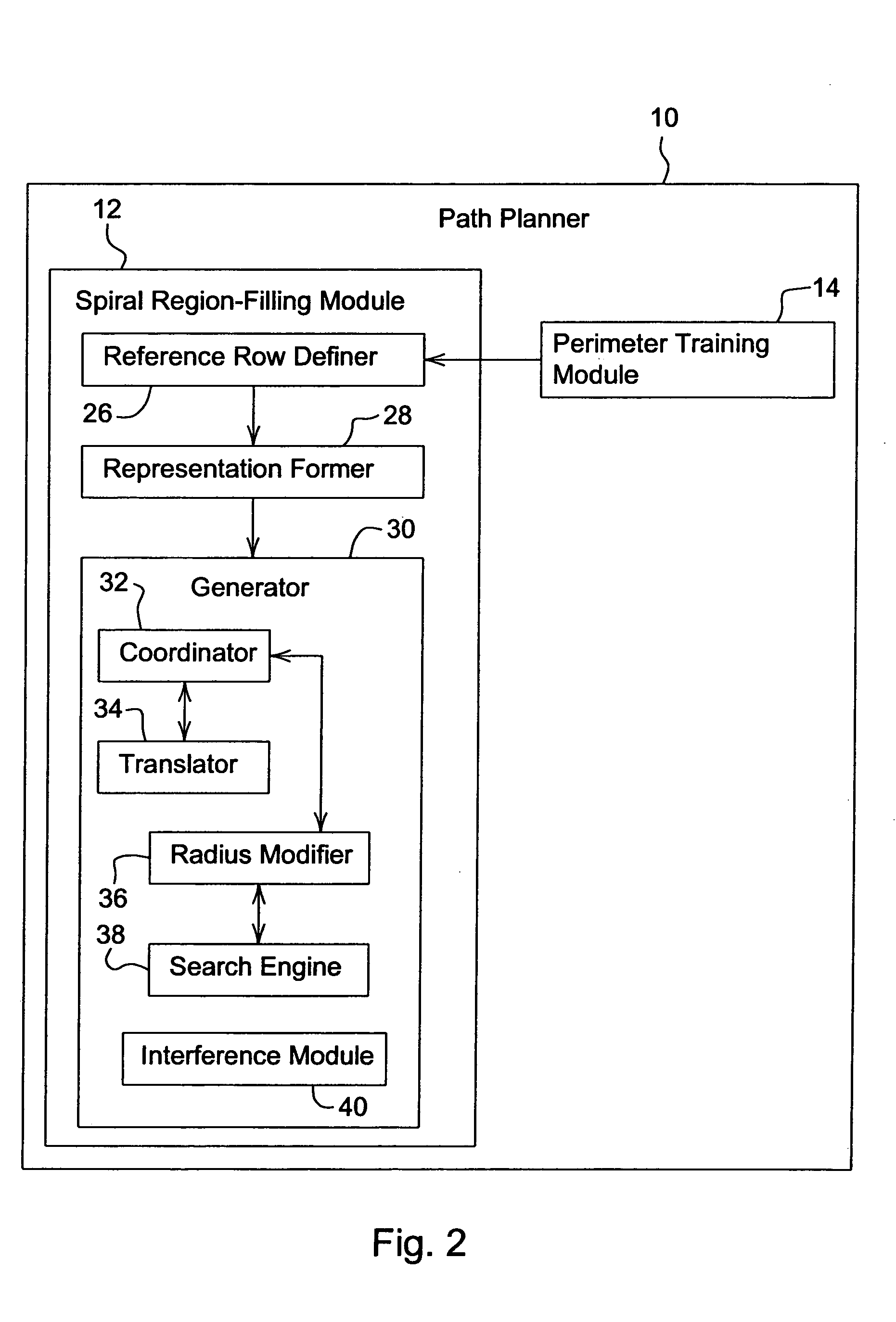
[0024]The path planner 10 of FIG. 1 comprises a perimeter training module 14 and spiral regio...


PUM


Abstract

A method and path planner for planning a path of a vehicle comprising a perimeter training module for identifying a border of a region associated with a work area. A definer for defining a reference row having a reference path that tracks at least a majority of the border. A generator generates tracking rows that track the reference row. The tracking rows comprise at least one inner tracking row and an outer tracking row. Each inner tracking row having at least one inner curve with a lesser radius than an outer tracking row having a corresponding outer curve with a greater radius.

Description

[0001]This application is a continuation-in-part of U.S. application Ser. No. 10 / 446,345, filed May 28, 2003, now U.S. Pat. No. 6,934,615 and entitled METHOD AND SYSTEM FOR DETERMINING AN EFFICIENT VEHICLE PATH, which is a continuation-in-part of U.S. application Ser. No. 10 / 403,681, filed Mar. 31, 2003, now U.S. Pat. No. 7,010,425, and entitled, A PATH PLANNER AND A METHOD FOR PLANNING A PATH OF A WORK VEHICLE.FIELD OF THE INVENTION[0002]This invention relates to a path planner and a method for planning a path having a spiral component.BACKGROUND OF THE INVENTION[0003]A path planner may be used to determine one or more path plans for a vehicle to cover a work area. The work area may represent a field for growing a crop or other vegetation. The vehicle may need to traverse the entire work area or a portion thereof to plant a crop (or precursor thereto), to treat a crop (or precursor thereto), to harvest a crop, or to perform another task associated with the crop or vegetation, for e...

Claims


Application Information

Patent Timeline
Patent Type & Authority Patents(United States)
IPC IPC(8): G01C22/00G05D1/00A01B69/04
CPCA01B69/008G05D1/0219G05D1/024G05D1/0255G05D1/0257G05D2201/0201
Inventor FLANN, NICHOLAS SIMONHANSEN, SHANE LYNNGRAY, SARAH ANN
Owner DEERE & CO
Why Eureka
Try Eureka