Capacitance measurement circuit

a capacitance measurement and circuit technology, applied in the direction of capacitance measurement, resistance/reactance/impedence, instruments, etc., can solve the problem of difficult to separately measure each component of the measuring target capacitance, and achieve the effect of improving the verification accuracy of a circuit simulator using a ring oscillator

Inactive Publication Date: 2007-06-12
RENESAS ELECTRONICS CORP +1
View PDF9 Cites 24 Cited by
  • Summary
  • Abstract
  • Description
  • Claims
  • Application Information

AI Technical Summary

Benefits of technology

[0015]As a result, the capacitance of the ring load section accompanying the first terminal is detected accurately. Therefore, the AC verification accuracy of a circuit simulator using a ring oscillator is improved, based on the accurately measured capacitance of the ring load section.

Problems solved by technology

Thus, it is difficult to separately measure each component of the measuring target capacitance.

Method used


Image

  • Capacitance measurement circuit
  • Capacitance measurement circuit
  • Capacitance measurement circuit

Examples


second preferred embodiment

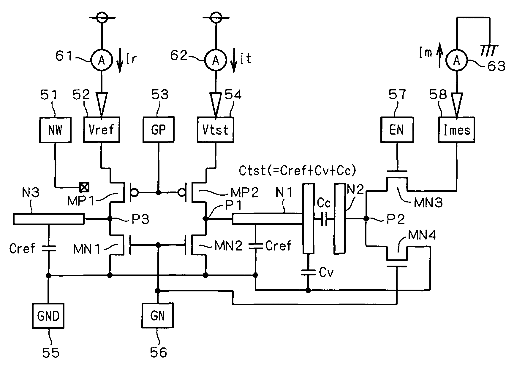
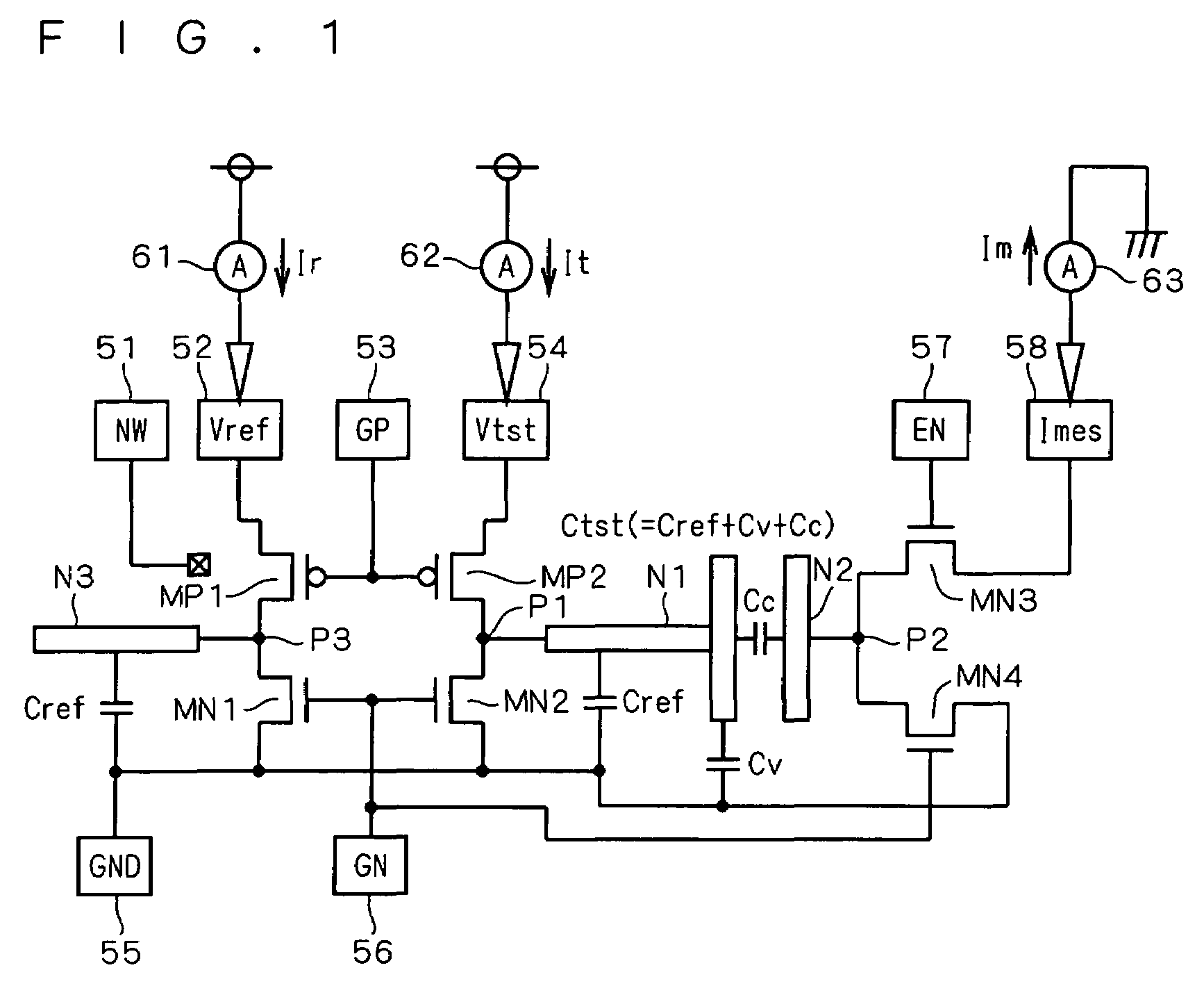
[0124]FIG. 5 is an explanatory diagram schematically showing, in relation to a well region, a configuration of a CBCM circuit according to a second preferred embodiment of the present invention. As shown in the drawing, the PMOS transistors MP1 and MP2 are formed in an N well region 32N, and the NMOS transistors MN3 and MN4 are formed in a P well region 32P. The potential of the P well region 32P is fixed at a P well ground potential PW by the pad 59. The other parts of the configuration are identical to those in the first preferred embodiment shown in FIG. 1 and thus not described herein.

[0125]FIG. 6 is a cross-sectional view showing cross-sectional configurations of the NMOS transistors MN3 and MN4 employed in the CBCM circuit of FIG. 5. FIG. 7 is an explanatory diagram simply illustrating a well structure of FIG. 6.

[0126]As shown in these drawings, a bottom N well region 31 is formed in the upper layer of a P-type substrate 30, and the P well region 32P and the N well region 32N ...

third preferred embodiment

[0132]FIG. 8 is a cross-sectional view showing a transistor structure employed in a CBCM circuit according to a third preferred embodiment of the present invention. As shown in the drawing, the NMOS transistors MN3 and MN4 are formed in an SOI (Silicon-On-Insulator) layer 43 of an SOI substrate which is formed of a P-type substrate 41, a buried oxide film 42 and the SOI layer 43.

[0133]In the SOI layer 43, N+ diffusion regions 44 and 45 are selectively formed. The gate electrode 37 is formed above the SOI layer 43 between the N+ diffusion regions 44, and the gate electrode 38 is formed above the SOI layer 43 between the N+ diffusion regions 45. The N+ diffusion regions 44 and the gate electrode 37 form the NMOS transistor MN4, and the N+ diffusion regions 45 and the gate electrode 38 form the NMOS transistor MN3.

[0134]The N+ diffusion region 44 (on the source side) is electrically connected through a contact hole 66 to the pad 55, the gate electrode 37 is electrically connected throu...

fourth preferred embodiment

[0139]FIG. 9 is a circuit diagram showing a configuration of a first circuit in a CBCM circuit according to a fourth preferred embodiment of the present invention. As shown in the drawing, a target capacitance forming part 91A for measurement of contact-to-gate capacitance is formed between the nodes N1 and N2. The other parts of the configuration are identical to those in the first preferred embodiment shown in FIG. 1 and thus not described herein.

[0140]FIG. 10 is a plan view showing an internal structure of the target capacitance forming part 91A according to the fourth preferred embodiment. FIG. 11 is a cross-sectional view taken along line X1–X1′ of FIG. 10.

[0141]As shown in these drawings, in the target capacitance forming part 91A, N+ diffusion regions 22, 23 and a P+ diffusion region 24 are selectively formed in the surface of a P well region 21, and the node N2 serving as a gate electrode is formed above the P well region 21 between the N+ diffusion regions 22 and 23. These ...


PUM


Abstract

A CBCM circuit is capable of separately measuring each component of a measuring target capacitance. A node (N1) is electrically connected to a terminal (P2) between the drains of PMOS and NMOS transistors (MP2, MN2). As a target capacitance forming part, a coupling capacitance (Cc) is formed between the node (N1) and a node (N2). The node (N2) is connected to a pad (58) through the terminal (P2) and an NMOS transistor (MN3), and a node (N3) is connected to a terminal (P3) between the drains of PMOS and NMOS transistors (MP1, MN1). A reference capacitance (Cref) is formed at the node (N3) as a dummy capacitance. Currents (Ir, It) supplied from a power source to the nodes (N3, N1) are measured with current meters (61, 62), respectively and a current (Im) induced from the node (N2) and flowing to a ground level is measured with a current meter (63).

Description

BACKGROUND OF THE INVENTION[0001]1. Field of the Invention[0002]The present invention relates to a CBCM (Charge-Based Capacitance Measurement) circuit using a CBCM technique, and a capacitance measurement technique using the CBCM circuit.[0003]2. Description of the Background Art[0004]The CBCM circuit is a capacitance measurement circuit with sub-fF (10−15 F or less) sensitivity that is difficult to achieve with AC current meters such as an LCR meter with sufficient accuracy, and is disclosed in James C. Chen et. al., “An On-Chip Attofarad Interconnect Charge-Based Capacitance Measurement (CBCM) Technique,” IEDM Technical Digest, 1996, pp. 69–72. Further, an improved CBCM circuit that is capable of separately measuring parts of capacitance in an interconnect configuration is disclosed in U.S. Pat. No. 6,300,765.[0005]In the conventional and improved CBCM circuits, a measuring target capacitance is predetermined; for example, a total capacitance or parts of capacitance in an intercon...

Claims


Application Information

Patent Timeline
Patent Type & Authority Patents(United States)
IPC IPC(8): G01R27/26G01R27/02
CPCG01R27/2605
Inventor KUNIKIYO, TATSUYAWATANABE, TETSUYAKANAMOTO, TOSHIKIYAMASHITA, KYOJI
Owner RENESAS ELECTRONICS CORP
Why Eureka
Try Eureka