
Voltage controlled oscillator with gain control

a voltage controller and gain control technology, applied in the field of electrical devices, can solve the problems of large percentage, difficult to keep the vco gain within a specified range, and large gain

Active Publication Date: 2007-06-12
NXP USA INC
View PDF5 Cites 12 Cited by
  • Summary
  • Abstract
  • Description
  • Claims
  • Application Information

AI Technical Summary

Benefits of technology

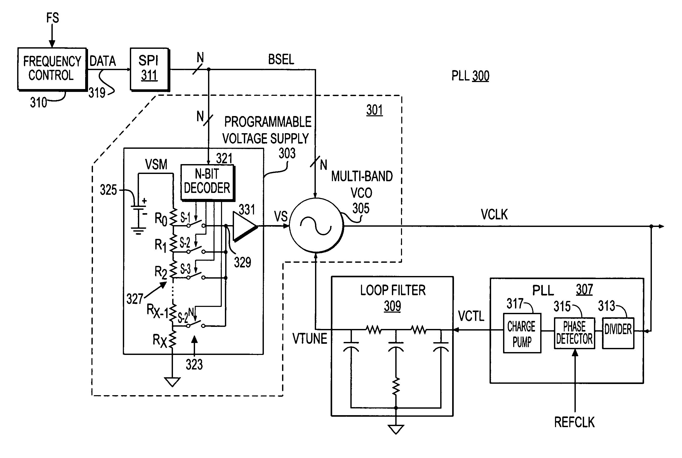
The present invention relates to a voltage controlled oscillator (VCO) circuit with low noise gain control for use in electronic devices, such as mobile phones and wireless transceivers. The invention aims to maintain a constant gain factor (KV) over the entire operable frequency range of the VCO, and to enable calibration of the KV at any time during operation and over operating temperature ranges. The invention also provides a VCO for a wide range of applications, including modern wireless transceivers. The invention includes a circuit design that reduces the impact of current source noise and enables the design of fully integrated, multi-band direct-conversion transmitters for existing and future wireless and wireline applications.

Problems solved by technology

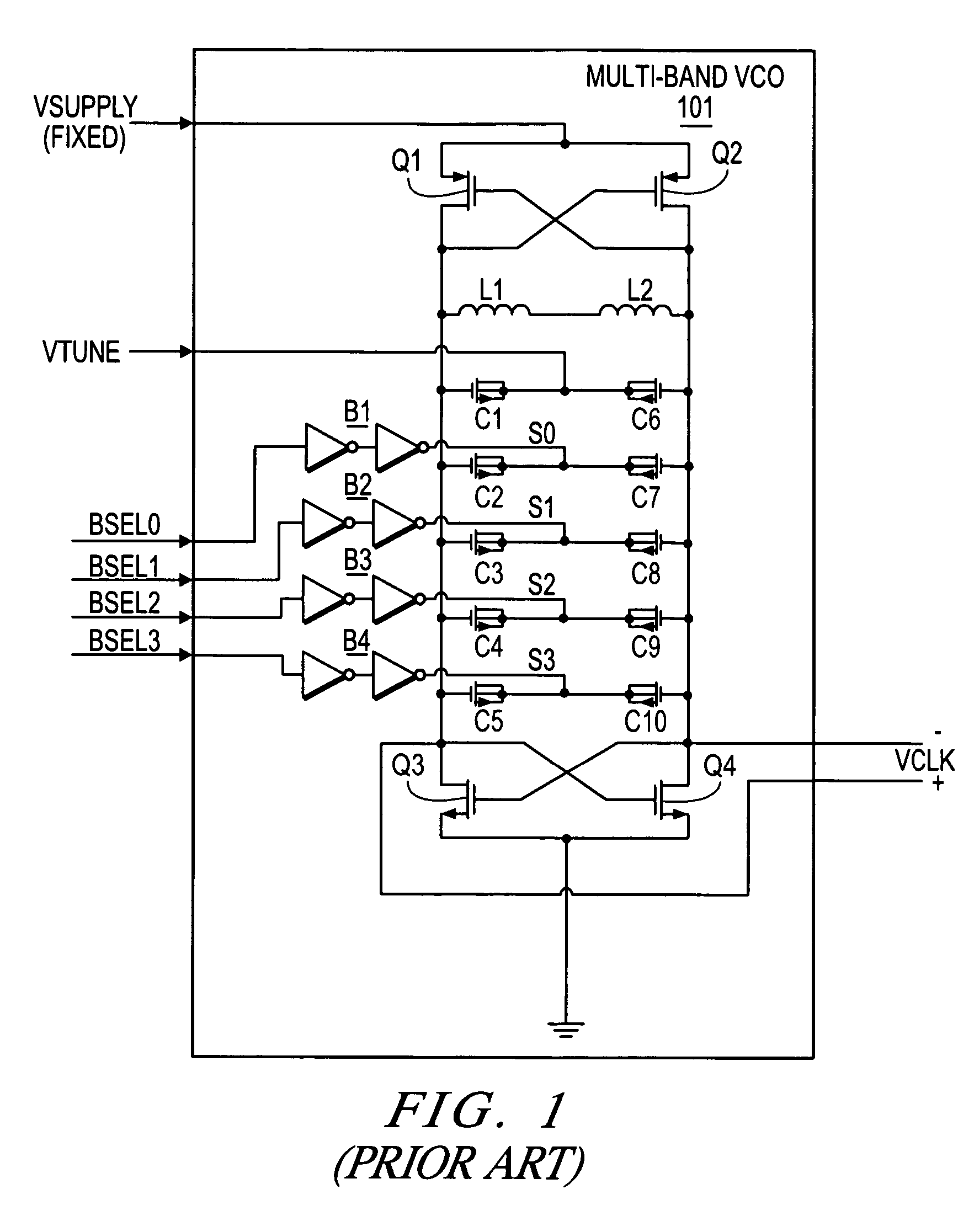
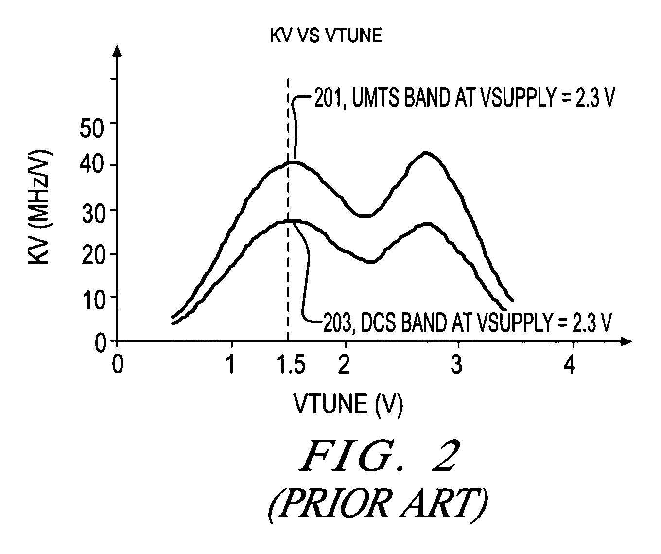
It has been very difficult to keep the VCO gain within a specified range when band switching over a large frequency range.
The problem of maintaining a relatively constant gain is compounded by the fact that a single discrete PLL filter is typically used for all bands on the same printed circuit board (PCB).
It has been determined, however, that a very large percentage (e.g., approximately 70%) of the noise in conventional VCOs is attributable to this current source.

Method used


Image

  • Voltage controlled oscillator with gain control
  • Voltage controlled oscillator with gain control
  • Voltage controlled oscillator with gain control

Examples


Embodiment Construction

[0016]The following description is presented to enable one of ordinary skill in the art to make and use the present invention as provided within the context of a particular application and its requirements. Various modifications to the preferred embodiment will, however, be apparent to one skilled in the art, and the general principles defined herein may be applied to other embodiments. Therefore, the present invention is not intended to be limited to the particular embodiments shown and described herein, but is to be accorded the widest scope consistent with the principles and novel features herein disclosed.

[0017]The terms “a” or “an”, as used herein, are defined as one or more than one. The term “plurality”, as used herein, is defined as two or more than two. The term “another”, as used herein, is defined as at least a second or more. The terms “including” and / or “having”, as used herein, are defined as comprising (i.e., open language). The term “coupled”, as used herein, is defi...


PUM


Abstract

A VCO circuit including a VCO, a voltage supply and a control circuit. The VCO has a supply voltage input and a gain that changes with its supply voltage. The voltage supply has an adjust input and an output coupled to the supply voltage input of the VCO. The voltage supply adjusts the voltage level of its output in response to changes of the adjust input. The control circuit has a first adjust output coupled to the adjust input of the voltage supply to adjust the gain of the VCO. The VCO may include a frequency range adjust input controlled by the control circuit so that the gain of the VCO is adjusted when the frequency range is changed. For a multi-band VCO, the gain is adjusted for different frequency bands to maintain a relatively constant gain for each frequency band.

Description

BACKGROUND OF THE INVENTION[0001]1. Field of the Invention[0002]The present invention relates in general to electronic devices, and more specifically to a voltage controller oscillator circuit with low noise gain control.[0003]2. Description of the Related Art[0004]Many different frequency bands are known and in use today for mobile wireless applications, including the Universal Mobile Telecommunications System (UMTS) band operating in the 1.920–2.170 gigahertz (GHz) frequency range, the Personal Communications Services (PCS) band operating in the 1.850–1.990 GHz frequency range, the Digital Communications Services (DCS) band operating in the 1.710–1.880 GHz frequency range, the “900 band” operating in the 880–960 megahertz (MHz) frequency range, the “800 band” operating in the 824–894 MHz frequency range, etc., where each listed frequency band includes both transmit and receive frequencies. Mobile phone manufactures often need to design phones that are operable in multiple frequenc...

Claims


Application Information

Patent Timeline
Patent Type & Authority Patents(United States)
IPC IPC(8): H03B5/00H03L7/099
CPCH03L7/099H03L7/10H03L2207/06H03L7/103
Inventor RACHEDINE, MOHAMMEDKACZMAN, DANIEL L.
Owner NXP USA INC
Learn More