Multistandard video decoder and decompression system for processing encoded bit streams including a video formatter and methods relating thereto

a video decoding and decompression system technology, applied in the field of multi-standard video decoding and decompression system for processing encoded bit streams including video formatters, can solve the problems of inflexibility in the overall system and subsystem, and the number of other inefficiencies

Inactive Publication Date: 2007-06-12
CHARTOLEAUX
View PDF203 Cites 69 Cited by
  • Summary
  • Abstract
  • Description
  • Claims
  • Application Information

AI Technical Summary

Benefits of technology

[0262]The suitability of the two-wire interface, in accordance with the present invention, for such “state machine” circuits is a significant advantage of the invention. This is especially true where a data path is being controlled by a state machine. In this case, the two-wire interface technique above-described may be used to ensure that the “current state” of the machine stays in step with the data which it is controlling in the pipeline.
[0263]FIG. 6 shows a simplified block diagram of one example of circuitry included in a pipeline stage for decoding a token address field. This illustrates a pipeline stage that has the characteristics of a “state machine”. Each word of a token includes an “extension bit” which is HIGH if there are more fords in the token or LOW if this is the last word of the token. If this is the last word of a token, the next valid data word is the start of a new token and, therefore, its address must be decoded. The decision as to whether or not to decode the token address in any given word, thus, depends upon knowing the value of the previous extension bit.
[0264]For the sake of simplicity only, the two-wire interface (with the acceptance and validation signals and latches) is not illustrated and all details dealing with resetting the circuit are omitted. As before, an 8-bit data word is assumed by way of example only and not by way of limitation.
[0265]This exemplifying pipeline stage delays the data bits and the extension bit by one pipeline stage. It also decodes the DATA Token. At the point when the first word of the DATA Token is presented at the output of the circuit, the signal “DATA_ADDR” is created and set HIGH. The data bits are delayed by the latches LDIN and LDOUT, each of which is repeated eight times for the eight data bits used in this example (corresponding to an 8-input, 8-output latch). Similarly, the extension bit is delayed by extension bit latches LEIN and LEOUT.
[0266]In this example, the latch LEPREV is provided to store the most recent state of the extension bit. The value of the extension bit is loaded into LEIN and is then loaded into LEOUT on the next rising edge of the non-overlapping clock phase signal PH1. Latch LEOUT, thus, contains the value of the current extension bit, but only during the second half of the non-overlapping, two-phase clock. Latch LEPREV, however, loads this extension bit value on the next rising edge of the clock signal PH0, that is, the same signal that enables the extension bit input latch LEIN. The output QEPREV of the latch LEPREV, thus, will hold the value of the extension bit during the previous PH0 clock phase.
[0267]The five bits of the data word output from the inverting Q output, plus the non-inverted MD[2], of the latch LDIN are combined with the previous extension bit value QEPREV in a series of logic gates NAND1, NAND2, and NOR1, whose operations are well known in the art of digital design. The designation “N_MD[m] indicates the logical inverse of bit m of the mid-data word MD[7]. Using known techniques of Boolean algebra, it can be shown that the output signal SA from this logic block (the output from NOR1) is HIGH (a “1”) only when the previous extension bit is a “0” (QPREV=“0”) and the data word at the output of the non-inverting Q latch (the original input word) LDIN has the structure “000001xx”, that is, the five high-order bits MD[7]–MD[3] bits are all “0” and the bit MD[2] is a “1” and the bits in the Zero-one positions have any arbitrary value.

Problems solved by technology

They have also suffered from a number of other inefficiencies and inflexibility in overall system and subsystem design and data flow management.

Method used


Image

  • Multistandard video decoder and decompression system for processing encoded bit streams including a video formatter and methods relating thereto
  • Multistandard video decoder and decompression system for processing encoded bit streams including a video formatter and methods relating thereto
  • Multistandard video decoder and decompression system for processing encoded bit streams including a video formatter and methods relating thereto

Examples


Embodiment Construction

)

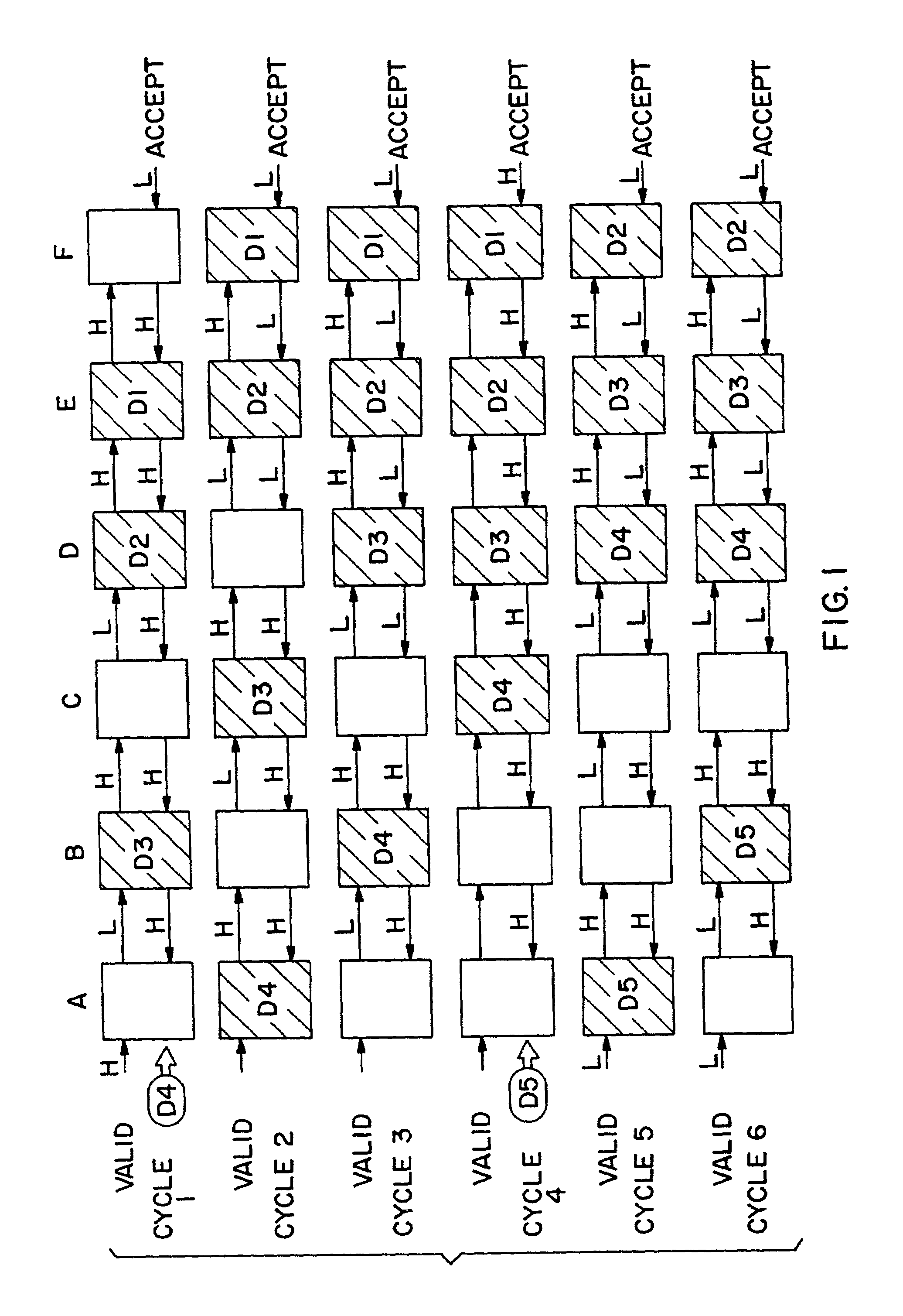
[0139]As an introduction to the most general features used in a pipeline system which is utilized in the preferred embodiments of the invention, FIG. 1 is a greatly simplified illustration of six cycles of a six-stage pipeline. (As is explained in greater detail below, the preferred embodiment of the pipeline includes several advantageous features not shown in FIG. 1.).

[0140]Referring now to the drawings, wherein like reference numerals denote like or corresponding elements throughout the various figures of the drawings, and more particularly to FIG. 1, there is shown a block diagram of six cycles in practice of the present invention. Each row of boxes illustrates a cycle and each of the different stages are labelled A–F, respectively. Each shaded box indicates that the corresponding stage holds valid data, i.e., data that is to be processed in one of the pipeline stages. After processing (which may involve nothing more than a simple transfer without manipulation of the data) valid...


PUM


Abstract

A pipeline video decoder and decompression system handles a plurality of separately encoded bit streams arranged as a single serial bit stream of digital bits and having separately encoded pairs of control codes and corresponding data carried in the serial bit stream. The pipeline system employs a plurality of interconnected stages to decode and decompress the single bit stream, including a start code detector. When in a search mode, the start code detector searches for a specific start code corresponding to one of multiple compression standards. The start code detector responding to the single serial bit stream generates control tokens and data tokens. A respective one of the tokens includes a plurality of data words. Each data word has an extension bit which indicates a presence of additional words therein. The data words are thereby unlimited in number. A token decode circuit positioned in certain of the stages recognizes certain of the tokens as control tokens pertinent to that stage and passes unrecognized control tokens to a succeeding stage. A reconfigurable decode and parser processing means positioned in certain of the stages is responsive to a recognized control token and reconfigures a particular stage to handle an identified data token. Methods relating to the decoder and decompression system include processing steps relating thereto.

Description

CROSS REFERENCE TO RELATED APPLICATIONS[0001]This application is a divisional application of U.S. Ser. No. 09 / 775,518 filed on Feb. 5, 2001, which is a divisional of U.S. Ser. No. 09 / 307,239 filed Oct. 7, 1997, which is a continuation of U.S. Ser. No. 08 / 400,397 filed Mar. 7, 1995 now abandoned, which is a Continuation-In-Part of U.S. Ser. No. 08 / 382,958 filed Feb. 2, 1995, now abandoned, which is a continuation of U.S. Ser. No. 08 / 082,291 filed Jun. 24, 1993, now abandoned.BACKGROUND OF THE INVENTION[0002]The present invention is directed to improvements in methods and apparatus for decompression which operates to decompress and / or decode a plurality of differently encoded input signals. The illustrative embodiment chosen for description hereinafter relates to the decoding of a plurality of encoded picture standards. More specifically, this embodiment relates to the decoding of any one or the well known standards known as JPEG, MPEG and H.251.[0003]A serial pipeline processing syst...

Claims


Application Information

Patent Timeline
Patent Type & Authority Patents(United States)
IPC IPC(8): H04N7/12H04B1/66H04N11/02H04N11/04G06F9/38G06F9/44G06F12/02G06F12/04G06F12/06G06F13/16G06F13/28G06T9/00H04N7/26H04N7/50
CPCG06F9/3867G06F9/4436G06F12/0207G06F12/04G06F12/0607G06F13/16H04N19/423G06F13/1689G06F13/28H04N19/61H04N19/91H04N19/42G06F13/1673G06F9/4494
Inventor WISE, ADRIAN PSOTHERAN, MARTIN WROBBINS, WILLIAM PJONES, ANTHONY MFINCH, HELEN RBOYD, KEVIN J.CLAYTON, ANTHONY PETER J
Owner CHARTOLEAUX
Why Eureka
Try Eureka